Barom 58 Panel - Arduino Interface
Arduino code
When starting this Baron 58 project we wrote lots of test code for Arduino, to clarify all aspects of data exchange between Arduino and X-Plane, initially using only X-Plane's inbuilt Ethernet UDP protocol of X-Plane, without plugin or any other software and library.
You can take o look at few of these early programs in the "Code Archive", where you will see the evolution of Arduino I/O interface for our Baron project.
For this Baron-58 project Arduino "Mega-1280" board coupled with Ethernet shield was used. To extend the number of inputs we made a DIY extention board for 128 inputs, as well as the board with output registers for LED indicators (serial output from Arduino):


Note: The input extension method described here was designed specifically for our Baron 58 project and should NOT be considered as the only possible or recommended option for your own cockpit project!
You may use our latest SimVimCockpit interface without the need to program Arduino.
Library and plugin
Later, since summer 2014 all this work and test sketches were revised and organized in a single Arduino library (XPData, closed project) that included functions for network interaction between Arduino and X-Plane, functions for receiving and decoding any of X-Plane incoming data, and functions for transmitting data to X-Plane. It makes Arduino programming for users as simple as possible - you only need to define the pin number and its function (button, switch, encoder, axis, etc.).
The Arduino program monitors all inputs in each cycle, but if no changes were detected, it does not transmit anything to X-Plane. if the program detects that the position of any of the controls was changed, it immediately sends the specific packet via Ethernet. In general, the whole process of data sending (in the newest B58 code editions) takes 1-5 milliseconds in one cycle.
In the last versions of the Baron code the XPData library is used and data from X-Plane is received via ArdSim plugin (without the need to define data groups for output in the "Data Input/Output" X-Plane menu).
Currently our Baron 58 is frozen being in a process of migrating to SimVimX interface..
I/O Extension boards
DIY 128 inputs extension for Arduino
To extend I/O capability of microcontroller, common "key matrix" technique can be used. But for the Baron-58 project I decided to use a parallel input bus interface, because this is convenient and easy way that I have used in my electronics practice.
Using just 8 Arduino pins as inputs plus 4 as outputs we have 128 inputs (this technique could be used for outputs too).
The diagram below shows how to use 8-bit bus transceivers (x16) and one demultiplexer for inputs extension.
The extension board needs to be powered from a separate supply! (not from Arduino). Good choice is to use some old PC Power supply (AT) for +5v bus.Description
This system consists of an 8-bit bus and 16 8-bit ports connected to it. Only one of the 16 ports is connected to the bus at any given moment. The program code for reading all 128 inputs is running in each cycle (about 1.5 ms) and the status of all inputs is firstly stored in the 16-byte array. Then the stored data is checked for changes and processed for further transmitting to X-Plane.
Schematic for 128 inputs:
Diagram: using 16 8-bit bus transceivers with multiplexer for inputs extension
Instead of 8283A (8282A) any functionally similar ICs could be used such as: PB 8287, 74LS245, etc. 8283A (8282A) is a register with LATCH. An STB signal (on pin #11) latches data when it falls from high to low level and is not needed in this circuit (it always is in high level).
We need only the -OE signal to set inactive ICs outputs to high-impedance level (only one is chosen at any moment). As we don't need the LATCH function here, you can use any of the common octal bus transceivers, such as 74LS245 and 8287: (the 8287 is very similar to 8283 IC with the same pinouts, but it is a bi-directional bus transceiver and instead of STB it has T (dir) , which has to be in high level too to work as 8283)
The 245 is identical to 8287, but DIR (T) is on pin #1 (vs 11) and -OE on pin #19 (vs 9), on the opposite side of IC, also data pins are shifted. As for inversion, the function (in the XPData library) "BusScan (pin1, pin2, inv)" has a 3rd argument "inv" that defines what ICs will be used (0 = inverted, 1 = not inverted).
Using bidirectional 74LS245 ICs
The 74LS245 is a bi-directional bus transceiver, and it has DIR input which determines the direction of data flow.When DIR input is in low level (0), the data is transmitted from Bn to An:

Diagram: using 8-bit bus transceivers for input extension
If you have to connect "B" inputs to Arduino (if it is more suitable for your needs) the "DIR" input should be in high level:
When DIR input is in high level (1), the data is transmitted from An to Bn:
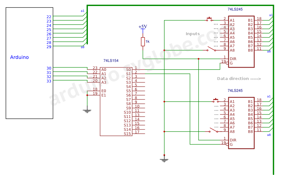
Diagram: 8-bit bus transceivers for input extension
Using bidirectional 74LS245 ICs for output and input extension
As we can choose the direction of data flow anytime with Arduino code putting the 74LS245 DIR input to "0" or "1" or latch data for register 8282A/8283A setting STB input to "0", so we can use mixed ICs and assign some ports for outputs using the 8282A (or 8283A LATCH register).Here the DIR input is in low level "0", when IC #1 is chosen for data reading and in high level when IC #2 is chosen for data output (the data is transmitted from Arduino to LEDs). When DIR/STB is "0" the 8282A IC will store data:
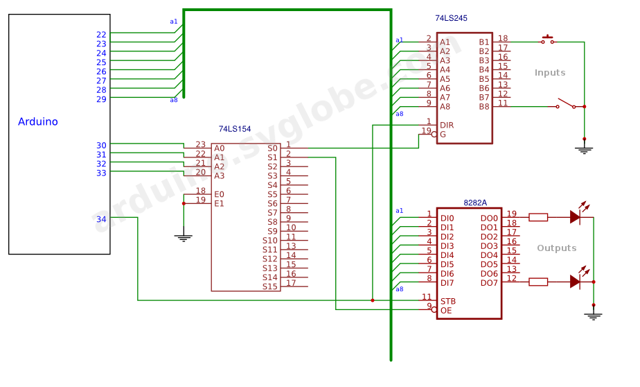
Diagram: using 8-bit bus transceivers and registers with latch for input/output extension