Digital Output / LED Indicators in SimVimX
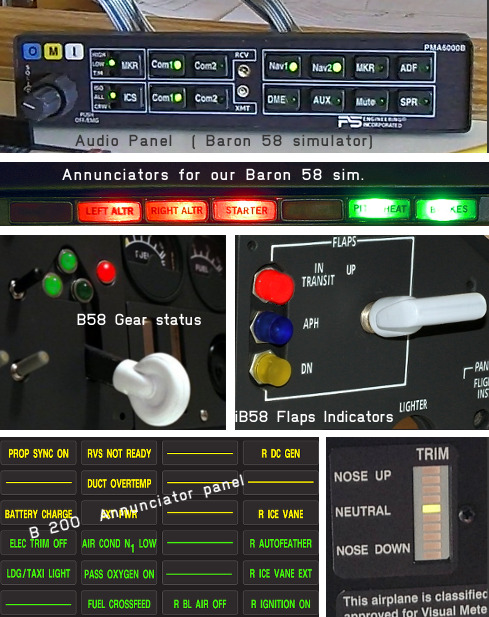
Digital outputs are a simple ON/OFF type of signals that can be used to control annunciators, lights, relays, power lines, flags - that is, all two-state output devices that are present in every aircraft cockpit.
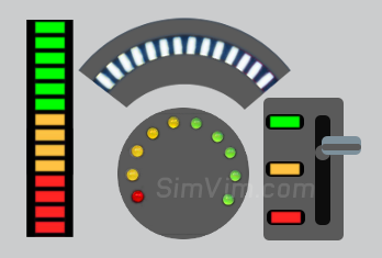
Multiple LEDs can be combined into one “bargraph” indicator to display the value of a numeric parameter. You can get one of those LED bargraph indicators present on the market in different sizes, colors and sector numbers (see below on this page).
Note that some indicators in your cockpit do not require receiving any data from the simulator for their operation. Often this can be an indicator that only shows the current switch position/state (not the system state!) and can be directly controlled by this switch, as most "korry-type" push-button switches).
Multiple LED Control, Serial output
The primary method for driving multiple LEDs in SimVimX is the "series-parallel shift" method using shift registers with latch (memory).
For this purpose, the SimVimX system uses 16-channel DM13A LED drivers, that also provides constant-current outputs for LEDs. Any other similar drivers listed on the "Components" page. can be used instead.
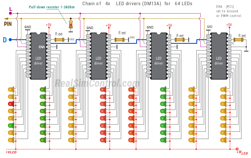
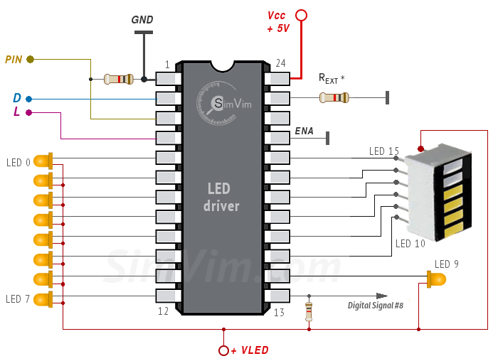
The wiring is quite simple - you need to connect common GND, 3 signal lines - two common "D/L" lines and one control signal "PIN" connected to the pin assigned in the config tool or multiplexer output:

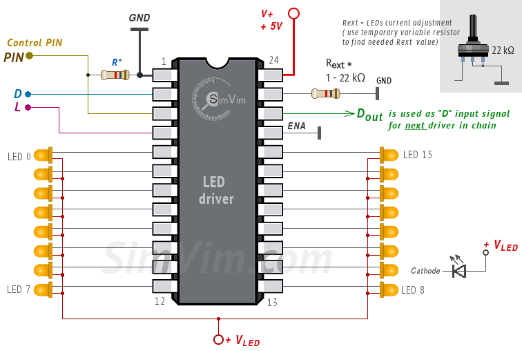
The driver has 16 constant current outputs and each single output can sink the current by 3 ... 60 mA. The LED operating current can be set with one reference resistor connected to the Rext input (terminal #23), that can have resistance between 1 ... 22 kΩ and defines the current (and brightness) for all LEDs. You can connect a variable resistor to adjust the current as needed and then replace it by a constant resistor.
The driver chip itself can be powered using +5V output pin located on the master board, but you amust use a dedicated source (+Vled +5V) for all LEDs powering. The amperage rate of this power supply must be sufficient to power all connected LEDs, for example, if one LED draws 20mA and you have 100 LEDs, the power supply must be rated at 2A, assuming they can all be lit at the same time.
Of course, you can simply use the same dedicated power supply +3.3 - 5V for all LEDs (+Vled) and chip's VDD (in this case don't connect VDD to the +5v pin on your Arduino!, only the GND should be wired together!).
Implementation options
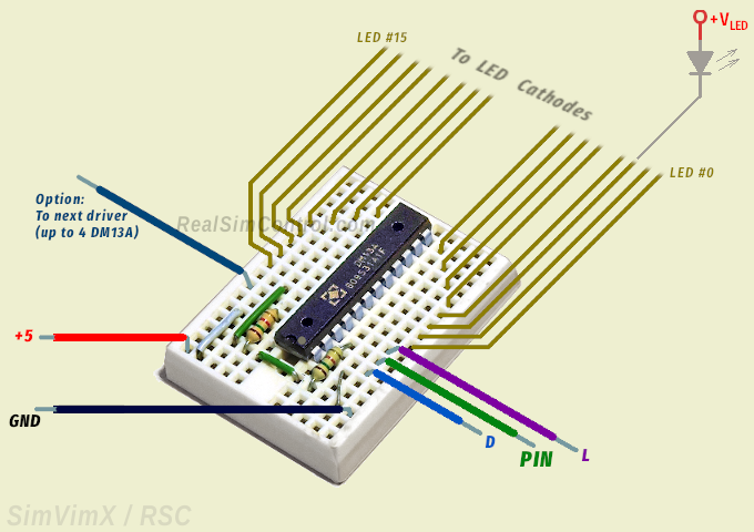
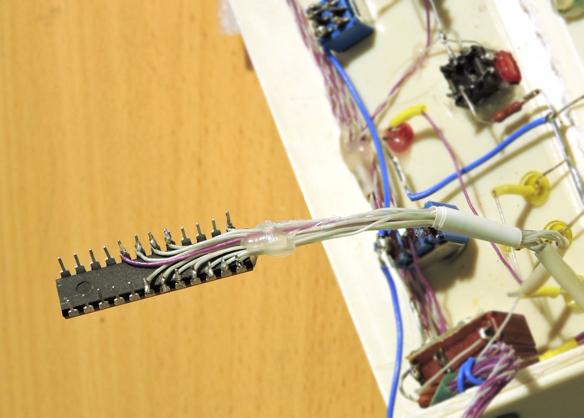
If you think you need to make PCBs for each driver or driver set, no, you don't necessarily need them. You can use a bare DM13A chip inserted into the small "breadboard" that can be taped to any part of your cockpit, or simply glued near to the group of LEDs ( see an example).
Also, using DM13A drivers in DIP casing, you can solder thin wires directly to the driver pins. Then this driver can be attached to the surface near the LED group using thermo-glue or 2-side duct tape.
See more tips about wiring your cockpit on the "Wiring" page.
Serial LEDs output capacity
In SimVimX system you can have from 8 to 64 serial LEDs connected to one output, depending on the location of LED groups in your panels. For example, you may have 16 LEDs controlled by one single DM13A driver connected to one pin, and another group of 30 LEDs controlled by 2 daisy-chain connected DM13A drivers on another pin.
The maximum number of LEDs with serial shift control on one output is 64, for that you can use 4 daisy-chain connected DM13A drivers. For this you need to use the driver's Dout terminal #22 as "D" input signal for next driver in chain:
As such, you can have either one or several separate LED groups located in different areas of your cockpit. Each group has 3 input signal lines (besides power lines). You need to connect the "PIN" input to the Master board pin assigned as extended output for this group of LEDs. Two other signal inputs - "D" and "L" - should be connected to the corresponding common bus lines ("D" and "L" output signals).
As the LED drivers alternative, you can use 8x shift registers, such as 74HC595 chips or breakout boards.
LED driver output used as digital output signal
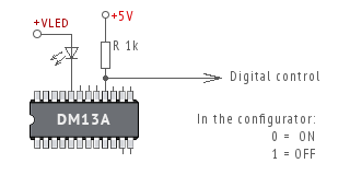
Same as for direct outputs, you can use a serial output as "On/Off" control signal for other circuits, relays, MOSFETs, etc.
For this, instead of LED, use a pull-up resistor 1k connected to +5v bus and use this terminal as output pin for digital control. In the picture you can see that output terminal #16 is used as digital output (all others can be used either for LEDs or digital outputs as well).
Using Output MUX
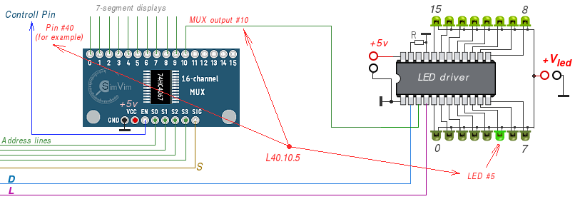
You can connect a Serial LED driver chain to the output multiplexer, that can be used for 7-segment displays at the same time. In the configurator, open the connected output multiplexer, then click an empty multiplexer output:
In the configurator image map or parameter table, select any parameter suitable for digital output (such as annunciator) or variable parameter for linear LED graph indicator, and assign it to one of the LED Driver outputs (from 0 to 63)
LED BarGraph Indicator
To display some parameter value as a linear or circle graph indicator you can assign it as "LED Bar Indicator (series of LEDs)" in the configurator. Then, you have to select only the output number to which the first LED will be connected and then insert the number of LEDs your indicator includes.
You can configure several digital outputs for a multiple-LED indicator to display the current value of any numeric parameter as a linear or circle graph. This can be just 3 separate LEDs for 3 positions or a LED bar indicator with 3 to 64 sectors. In this example diagram the LED bar with 6 sectors is connected to outputs #10 to #15, and output #8 is used as digital control signal for some other electronics:
All LEDs forming this indicator should be connected to the first specified digital output and all consequent outputs without skipping. You can use either separate LEDs arranged in the form you need (circle or linear) or LED bar graph indicators.
Note: The LED bar display modules with built-in voltage-controlled driver (like LM3914N) can not be used with digital outputs - you need to use PWM-controlled output for such displays instead.
LED-matrix Digital Output in SimVimX
Another method of controlling multiple LEDs is using a LED matrix. You can have up to 64 LEDs using one MAX7219 driver. It's the same driver that is used for 7-segment displays.
It is not "Serial LED output" - all diodes are connected as matrix or "grid". To make using LEDs with MAX7219 easier, you can buy one of the MAX7219 dot matrix module (example link), which also is very convenient for testing purposes because it has detachable LED dot-matrix module. To test all your assigned annunciators you can use this dot matrix and then detach it and connect two rows of wires (anodes, cathodes) that go to your LEDs connected as matrix grid.

Configuration
First, to "connect" the Matrix Max7219 driver in the configurator, click an empty pin (only #30-37 can be used) and select the "Add LED Matrix, Max7219" extension type
In the configurator image map or parameter table, select any parameter suitable for digital output (such as annunciator) or variable parameter for linear LED graph indicator, and assign it to one of the LED Matrix outputs (from 0 to 63).
Brightness Control
If you want to control the LEDs brightness, you can "link" the assigned LED matrix module with one of "BRT_*" knob in the configurator for any device with program-controlled brigtness.
3. Direct Digital Output control
When controlling the "On/Off" type of output device directly with controller pins all you should worry about is its power consumption. According to AVR tech spec, the maximum ("damage") current for a single pin in output mode starts with 40 mA, that is quite enough to drive most LEDs used as indicators. Likewise, any other directly connected device (actuator, integrated circuit, relays, etc) should sink the current no more than 20-40 mA.
- To use a common low-power LED, simply connect it to the pin (anode) and to the ground bus (cathode) using a series resistor that can vary from 100 Ω to 1 kΩ depending on the indicator brighntess you need.
- You can use a digital output as control signal for different integrated circuits and circuit boards. For example it can control a driver for high-power LEDs, or be used as an "On/Off" signal for 7-segment display, etc.
- Only a low-current relay coil can be controlled directly from the controller pin, otherwise you can use relay module that has a buffered input (with a transistor or optocoupler on its input).

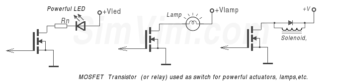
Powerful output devices that have high-voltage or high-current consumption cannot be controlled directly from microcontroller pins, you should always use some kind of buffer circuit for such devices.
This can be a PNP transistor, a MOSFET or a relay. If you use a relay, make sure that it has buffered input itself (as mentioned above) or it's a low current relay having a coil with higher resistance:
So, a single Mega2560 pin can be used as digital output when one output pin controls one LED. If your panel has just a few annunciators, you can simply connect the LEDs (or other digital devices) directly to Mega2560 board output pins, taking in account some limitations as described above. This is a simple, but inefficient method.
2. Option: Shift Registers used as serial LED driver
Though LED drivers DM13A (or equivalent) are more efficient and doesn't require a lot of current-limiting resistors as in case of simple shift registers, you can use 74HC595 8-bit shift registers if it is more appropriate for you (for example, you have completed modules with lot of common-cathode LEDs).
You can extend a digital output using up to 8 registers in series, or just one chip if you need to have only 8 outputs on the selected pin. When using HC595 ICs you need to connect each LED to the register output terminal with a resistor in series (resistor can be 300 Ω to 1 kΩ ). Three input signal lines - PIN, D and L are connected the same way as for LED driver described above.
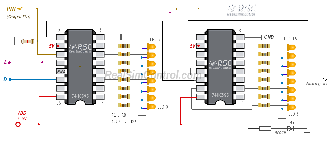

You can just buy several HC595 register ICs (about $1 for 10 ICs) and simply wire registers directly to the panel LEDs or make a printed board. The wiring diagram is here in the picture.
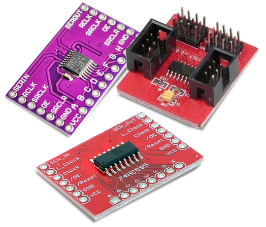
Another option is buying breakout boards with 74HC595 registers. You can find sample links on the "Components" page. All you need is to solder LEDs with resistors to the board outputs.