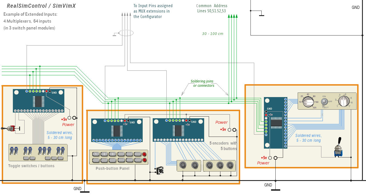
Input Extension Wiring
You need only 4 wires to connect all input multiplexers together using 4 common address lines: S0,S1,S2,S3 (or pins #22,23,24,25) and, of course you need to use 2 power lines - +5V and common Ground (GND) for all boards.
The SIG (can be labeled as "Z" on some boards) output of every input multiplexer should be connected directly to the pin assigned in the configurator for this input extension.

Note: The "EN" signal of each input extension board should be always logical "0" (set to GND). Usualy the multiplexer breakout board has a pull-down resistor on this 'EN" pin, so it can be already set to logical "0" but you need to be sure it is, so just connect it to GND.
The SimVimX firmware code algorithm guarantees fast and lossless readout of all input states, no matter how many inputs are assigned, and sends data packet to the plugin, which synchronizes data receiving/sending.
Wiring notes
The signal "SIG" (can be labeled as "Z") pad of every input multiplexer should be connected directly to the pin that need to be expanded. The most reliable way of wiring these extension modules is to place the board close to a group of switches and solder them with thin wires:


Signal interference issues
The input multiplexer signal output (SIG or "Z") directly wired to the master board input has high-impedance open state and the signal wire can catch some interference that depends on the electic noise level in power source lines and other surrounding wires. The RSC firmware sets all assigned input pins as inputs with internal 50 kΩ pull-up resistors, but it may not be effective enough, especially if you have a "noisy" electric environment in combination with rather long wires.
Thus, you need to place a pull-UP resistor (1 - 5 KOhm ) between MUX (SIG) output and +5V as shown in the picture above (on each input multiplexer breakout module directly). If you don't do this you may notice that some switches in your virtual plane cockpit are occasionally "flicking", one switch affecting another
Don't cosider this a switch bouncing problem, as SimVimX firmware code has full debounce protection and always check you have reliable common GND and power line, use soldering instead of using a lot of connectors.
Wiring, practical
Place the master board somewhere in the "middle" of your whole cockpit, in this case the length of all address wires will be no more than 1-2 meters. Also, I advise (as I always do) not to use any "extra" boards (PCBs), other than ready-to-use MUX boards, and to use soldering as I described above.
But if you already have such "additional" PCBs, do not use too many "detachable" connections/headers, especially if you have many of those boards that are daisy-chained (with go-through "in" and "out" connectors). This is very unreliable and can lead to multiple contact loss, can add a lot of resistance to all bus lines (due to oxidation of contacts), etc.
I recommend using the multiplexer boards as they are, fix each board near to the groups of switches and solder them with a bundle of 4 thin single-core wires (very clear wiring).


You can add multiple simple contact pads at different locations to branch the wires (you can solder another group of 4 wires to these pads in different directions, as I show in the right picture here as an example).
Modular wiring
Group a set of switches into one module/panel with multiplexer extension board placed close to all these switches. Make sure you have quite short wires from each button/switch or encoder to multiplexer inputs. Place several modules in different parts of your cockpit and connect them to the main board using only one pin for each multiplexer and the common 4 address wires that are laid across the cockpit to each multiplexer:
- Make sure that the GND wires of all devices and power supplies in your system are all connected to the common GND bus wire (the symbol
 is used as common ground wires for every device pictured on this website)!
 - Use +5V source (either from separate power supply or from the master controller board) to power all multiplexers. See more detail about system powering here.
- You can connect all your switch metal cases to the GND too (if they are mounted on a metal plate - simply ground this plate).

You can use some kind of wire splitters with reliable wire fastening, like these ones:
Example link 1(note, they are for the minimum wire size of 28AWG..)