Servo Control in SimVimX
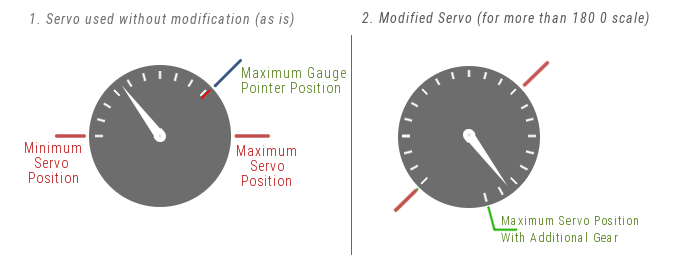
Using small RC hobby servos is an easy way to create most of mechanical instruments/gauges for your home cockpit. The only drawback can be that servos have some noise and limited range of shaft rotation (typical 180°)
As for noise, it is noticeable only at high speed, if the gauge is intended to show a slowly varying value, the noise will be insignificant. You can also find servos with minimal noise. The lomited range can be increased by adding a step-up gear (see desctoption below).
Servo controller
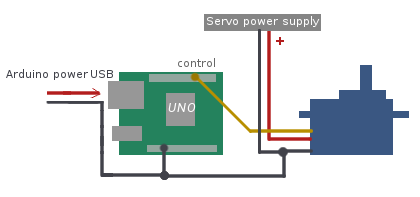
Multiple servos are controlled using additional SimVimX Servo controller board (Uno/Nano). SimVimX Servo Firmware is a program written from scratch to control multiple servos simultaneously anu you need tp upload it from the SimVimX plugin menu to this board.
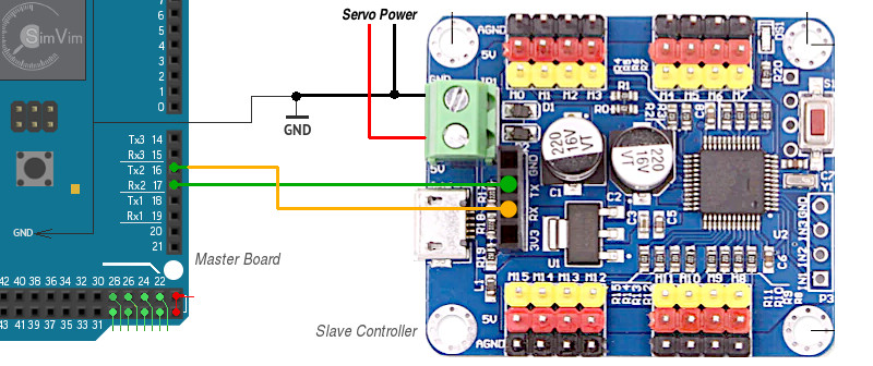
This "slave" controller board is connected with the Master board via serial interface, using Rx/Tx port #2 on the master board. Connect the Tx pin (#1) of the slave board with Rx2 pin (#17) of the master board, and "slave" Rx (pin 0) - with the "master" Tx2 (pin #16).
The master board transmits all data intendent for the servos to the slave board. The slave board firmware generates correct control pulses width for positioning multiple servos.
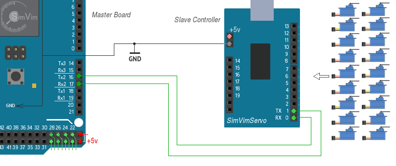
- Every servo is connected to one of the output pin available on the slave board starting from #2.
- You can connect up to 18 servos to the slave Servo board as shown in the right picture above.
Note 1. Never forget to connect the GNDs of each board ( and other devices as well) to the common GND wire.
Note 2: When you need to upload Servo control firmware to the slave board you need to disconnect the Rx,Tx wires before uploading! To simplify this you simply can add a "shut-off" switch breaking this two wires.
The slave board receives all data from the master controller board only. So, don't keep it connected to USB port after the SimVimX Servo firmware upload. You can use any +5V source connected to the slave board using USB connector, or +5V pin.
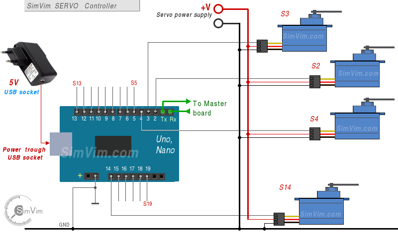
Servo powering
Servo has three wires: power, ground, and signal. The power wire is typically red/orange, the ground wire is black/brown and signal is yellow/white. Typically most servos have operating voltage range of 4.2 - 6 Volts.
For all servos used in your system (even if you have only 1-2 servos) you should always use an additional power supply! Even one single servo can sink several hundred milliamperes!
Use an external stabilized 1-10A DC power supply for servo powering! One of the best ways is using an old computer power supply. It can be any old AT PSU (its +5V output) that can be found in your garage.
Be sure to connect the "ground" wires of the controller board, servo and external power supply together first.
Servo gauges Configuration and Calibration
To assign any specific parameter for output to the servo, find this parameter in the configurator database and select it for servo output. Then select the needed servo number (pin number on the slave servo board).
Before using the servo-driven gauge in the cockpit you need to calibrate it. Use the convenient Calibration Tool in the SimVimX plugin to correctly map the data value range on the gauge dial.
! The control pulse width range can vary significantly for different servo brands. Even if you have several servos of one manufacturer all of them may have slightly different control ranges. So, when calibrating a particular servo in the plugin menu, watch carefully when the servo needle reaches it's edge positions. Usually the servo full angle range is 180 degrees.
Other Servo Controllers
Since v 0.9.34 the "WitMotion" 16, 24, 32-channel Servo Controller support is added and you can use them, connecting the same way as SimVimX Servo controller, as described above, with 2-wire serial interface (using pins #16,17). Note: you just need to connect it correctly, no "firmware" needed.
"WitMotion" controller is based on STM32 microcontroller, has high precision and stable timings and it's much better than using boards based on PWM drivers (PCA9685), which are not suitable for precise movement.
Here is the link to 16, 24, 32-channel servo controller board: [WitMotion Store on AliExpress].
NOTE: SimVimX Servo firmware for additional Uno/Nano is left as a cheaper option (only a spare Arduino board is needed), you can choose between these two options.
Using servo for your cockpit gauges

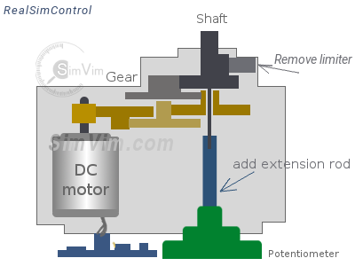
A typical servo has a small DC motor with metal or nylon drive gears to reduce rotation speed and increase torque. The output shaft can be rotated to a specific angle (or moved to a specific position for the linear servo) according to the pulse signal width.
The potentiometer on the shaft and a control circuit allow to monitor the angle of the shaft and turn the motor in the correct direction until the angle is correlated with the pulse width.
To properly control the servo drive, its internal circuit must receive a pulse every 20 ms. The width of this control pulse determines the angle of rotation for the servo and it can be in range of 0,5-2,5 ms (500-2500 us). Note that this range can vary for different brands, it can be 400-2000, or 1000-2500 etc. Even if you have several servos of one manufacturer all of them may have slightly different control ranges.
 Notes:
- Use powerful stabilized DC power supply for servo powering (not USB!)
- Typically most servos have Operating Voltage Range of 4.2 - 6 Volts
- Ensure you are using the optimal Voltage for your servo (+5v mostly is good)
- Be sure to connect the grounds of the controller, servo and power supply together.
- Servo has three wires: power, ground, and signal.
The power wire is typically red, the ground wire is typically black or brown
Calibrating the servo for specific instrument dial
Typically, a servo has 180° rotation range. If your gauge has lesser angle range (as some fuel gauges or some engine parameters gauges), just use a part of full servo shaft rotation. Print the dial for chosen instrument on the paper, place it on your servo, attach an arrow. Then calibrate this gauge in the SimVimX plugin.
Keep in mind that the minimum and maximum position value number can be correlated with the leftmost and rightmost positions of the servo arrow, or vice-versa. It depends on the particular servo model.If your instrument has a dial scale larger than 180° you can increase the angle range using 2 methods:
1. Replace internal potentiometer
Replace the internal potentiometer with another one with a large rotation angle (270-280°). You will need to remove (or change) the limiter for the output gear. The large potentiometer can be placed outside of servo casing. Make sure that the potentiometer's resistance change is linear, and that it has the same max resistance value as the original one. This is a very good method to use, especially when using a high-precision potentiometer.
2. Adding a step-up gear
Adding external step-up gear (e.g., 1.5:1 or 2:1 ), this method doesn't require to disassemble the servo, you need to find a couple of suitable gearwheels and make a support constuction for gear. Gear ratio can be from 1.5/1 to 2/1 to extend the servo rotation angle by 90-180°. Do not make the rotation angle of more than 360°.

Calibrating the servo for non-linear instrument dial
Some instrument has non-lineary scaled dials. In this case you can calibrate such servo gauge in the SimVimX plugin calibration menu adding more key points for several sectors on the gauge dial. Most non-linear scaled instrument dials are just divided into several linear segments.
In this case you should determine each segment and write them down for use in the library function for servo control.
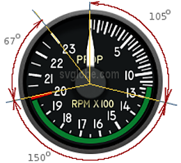
Let's take for example a typical B200 Prop Speed gauge. Its dial can be divided into three linear sectors - the first sector has 105° angle, the second 150°, the third 67°.
If a 2:1 step-up gear is used for the servo, we have a 360° arrow stroke and you can use it for such gauge and calibrate it for 4 key-points in the calibration menu. Actually, both 2nd and 3rd sector have the same scale (or almost same), this dividing was made to show the principle of using the "servoGauge" function for multi-scale gauges.
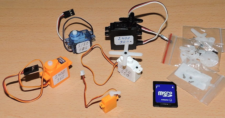
My servos:
Example of the servo gauge controlled by RPM dataref (this is old video from 2013, the servo controlled with our old ARDref plugin):
Example: Rudder trim position indicator for Baron 58
This example uses one encoder attached to the trim wheel and a servo that rotates the disk with the scale. The servo used here Rudder trim position indicator :Video on youtube