Analog axes
Simulator parameters that vary within a certain range can be controlled in two ways - using either relative (incremental) or absolute value change. In the first case, the value is changed step by step using an encoder or two +/- buttons, in the second case - using any absolute positioning sensor.
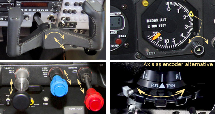
The SimVimX System uses resistive sensors connected to analog inputs (A0-A15) as a voltage divider (potentiometer) to control parameter values according to the position of controls such as primary flight controls, engine control levers, flaps or brakes handles.
Also, you can control such parameters as instrument lighting, trims, pointer position in some instruments (for example, radio altimeter), using analog sensors instead of rotary encoders.
You can use any sensors or sources that can provide changeable voltage level in range between 0 and 5V as a signal for analog inputs, but in general, simple, common potentiometers can be perfectly used as analog sensors for most of the simulator cockpit controls. The middle terminal of a potentiometer should be connected directly to analog input, and the two others to +5v and common GND bus.


The SimVimX plugin receives data from the master board and converts sensor movement range into the range of dataref values and sends a new value to X-Plane every time the sensor position is changed by one step of predifined precision (sensitivity).
Connection
Any suitable potentiometer with full-stroke resistance of 3k to 10k can be used. Actually you can use any pot, but with lower resistance the circuit is more tolerant to electrical noise from the power lines. In general, 5k potentiometer value is just fine.
You can use all analog pins to control up to 16 axes, but of course if you need only a few axes, any other analog pins can be used as digital inputs or outputs, direct or extended:

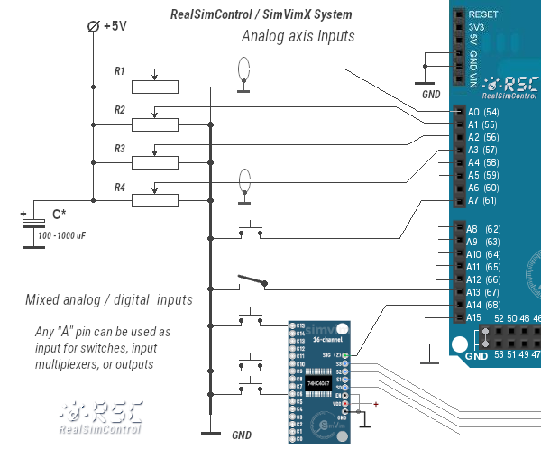
NOTE: along with a stabilized +5v power supply for all potentiometers, I recommend to add an electrolytic capacitor (500-1000uF) between +5v and GND close to the group of potentiometers, or directly solder the capacitor between gnd/5v legs of every pot (about 1000uF summary) if you have the pots in different distant places.
Configuration, calibration
To assign an analog input, find a parameter in the configurator that is suitable for it, open the then select desired analog Arduino pin in the [Axis] table.
No entry of additional options is required. The precision (sensitivity) and the dataref value range are pre-defined for each parameter, but can be changed with a conversion if needed.
If you have analog sensors with partial movement range in your cockpit, use the plugin's built-in "Analog Calibration" feature to configure them properly. The corresponding analog inputs must be included in the configuration file, and the plugin must establish connection with the Arduino board first.
After pressing the "Calibrate" button, move all analog sensor handles in your Cockpit in their full range (moving each of them into min/max positions once is enough). After you've done that, press "Finish". Now, the plugin will consider the movement ranges of your analog sensors to be the full range for the purposes of value mapping.
You only need to do this once, as long as the analog sensors remain connected to the same analog inputs, as their calibration data is saved into the plugin's axis configuration file.
Limited input sensor range
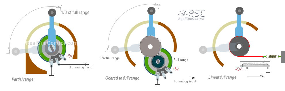
The full range of analog input is between 0 and +5v (0-100% in SimVimX ), but you may have a situation when you can't use the full range of sensor movement (e.g. when a potentiometer is fixed in place and has only a fraction of its full rotation angle used for the control lever). In this case input range can vary (0..3v, or 2..4v, and so on).
You can use a mechanical construction to extend the potentiometer move to full range, like using gears or a pulley-like design shown below.
The calibration function in SimVimX plugin helps you configure such sensors properly ("Calibrate analog" menu). The plugin will then convert the partial movement ranges of your analog sensors to the full value ranges.
Other sensors, or voltage level sources
You can also use some photoresistive or magnetoresistive sensors as signal source for analog input. Also, it can be any other signal source or electronics module that can provide variable voltage in range of 0..5v with needed precision.
Photoresistors
Using photoresistors is good for smooth control. First time I used this method for a DIY yoke in the late 90s using a 100k photoresistor connected to standard game port instead of a variable resistor.
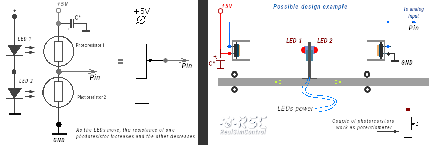
But when using the Arduino analog input, a differential pair of photoresistors is needed, connected as a voltage divider (like a potentiometer) and exposed to a light source (two opposite LEDs) that is moving toward one photocell away from another.
I've implemented this design in my Baron 58 panel.


This scheme is quite tolerant to ambient light change, as the ambient light affects both resistances, keeping the proportion the same. So, external lighting variation almost doesn't influence this setup. Also, both photoresistors are placed into small "tubes" to prevent direct light influence.
You can also try different mechanics, for example rotating (tilting) LEDs as I have shown in the diagram above on this page.