Input/Output Extensions
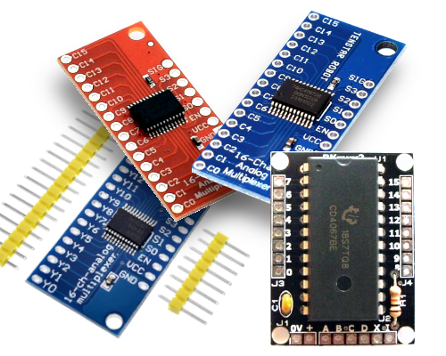
The widely available cheap CD74HC4067 multiplexer breakout board is used in the RSC/SimVimX system as main inputs extension. This multiplexer works as simple electronic "switch" when only one channel of 16 is selected with 4 address lines S0,S1,S2,S3 at any given time. The firmware functions very quickly scan all multiplexer inputs in every X-Plane frame and send all changes to the plugin.

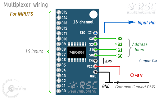
Thus, you can connect 16 toggle switches or momentary buttons to the multiplexer inputs, or use appropriate number of inputs for rotary switches and encoders. All multiplexers used for inputs are connected to 4 common address lines: S0,S1,S2,S3 (or pins #22,23,24,25).
Outputs Extension for 7-segment displays or LED drivers
To extend a number of 7-segment displays or LED drivers, the same CD74HC4067 module is used as reversed (output) multiplexer. You can use up to 4 multiplexers for output, but most likely only one-two output expansion boards will be sufficient for your entire system (32 displays).
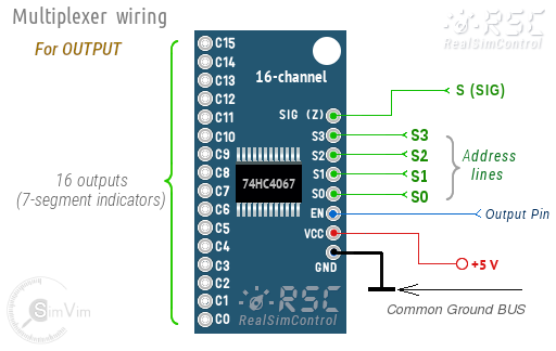
The difference from the input multiplexer is the connection and direction of signals, in this case the SIG (Z) is used as input, and all 16 channels are used as outputs:
- S0,S1,S2,S3 inputs are connected to the same common 4 address bus lines
- SIG ("Z") should be connected to the one "S" line on the master board
- "EN" input is connected to the output pin assigned for this output multiplexer board.
- C0..C15 outputs are used as input control signals for 7-segment indicators or LED drivers.
The SimVimX firmware program receives formatted data from the plugin that need to be changed for particular display. In the moment when needed channel is opened it sends data for output device connected to the selected channel.
Note: Any single extension board can be used either for inputs or outputs only! Don't try to connect switches to output multiplexer.
Other Output Extensions
- 1. SimVimX supports multiple serial outputs (up to 64x LEDs for one signal line), for this you need to use LED drivers or shift registers (see the details in the Wiring Guides).
- 2. SimVimX also supports "LED matrix output" (up to 64x LEDs for one output), for this you need to use the MAX7219 controller .
- 3. To extend the number of PWM outputs use one 24-channel PWM driver TLC5947 ).
Slave controller Boards
- 1. For stepper motors control additional SimVimX Stepper controller board is used. It is one Uno or Nano Arduino board with special stepper control firmware uploaded to it from the SimVimX plugin menu.
- 2. For servo control additional Servo controller board is used. It is one Uno or Nano Arduino board with special SimVimX Servo control firmware uploaded to it from the SimVimX plugin menu. Also you can use the WitMotion 16-32-channel Servo Controllers.
- 3. Support for Button Matrix Extension board, the "SimVimX Matrix" firmware is added and the "Matrix" board is included in the configurator.
NOTE: Though the main input/output connection options mostly stay intact, the configuration protocol and hardware connections can be changed, sometimes drastically.
You don't need to order or make some kind of complex PCBs, the SimVimX architecture is specially designed the way when anyone can simply buy ready-to-use, cheap modules and breakout boards listed on this website and in the "Components" page, connect them as described on our pages, that's all.
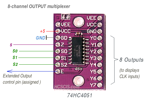
Option: 8-channel extension boards
You can also use the 8-channel 74HC4051 multiplexer when you don't need many switches (or 7-segment displays) in one particular place. There is no difference in code performance because the firmware function always counts it as 16-channel MUX.
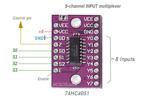
1) For 8-bit INPUT multiplexer board you should not connect the "EN" input to the "GND". Instead you need to use the first 3 bus address lines for S0..S2 and connect the 4-th address line to the "EN" input of this multiplexer board.
2) For 8-bit OUTPUT multiplexer board the address line S3 is not used at all.