Key Matrix
How to Connect
The additional (slave) "SimVim Matrix" controller board is Nano or Uno Arduino with special SimVimX Key-Matrix control firmware that you need to upload directly from the SimVimX plugin menu.
This board is connected with the Master controller board. The "SimVimX Matrix" firmware code of the slave board reads matrix grid state and sends it to the master board.
- You can make key matrix with up to 176 nodes, actually you can use any grid from 2x2 to 16 x11
- Only buttons can be used as input for matrix, not toggle switches or encoders.
- To assign a button as key-matrix input in the configurator click the "Matrix" button above the assignment table to select the key matrix table.
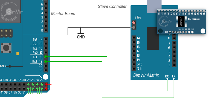
The "slave" controller board (Uno, Nano) is linked with the Master controller board using serial interface, when Tx output signal of one board is connected to the Rx iNput of another board.
For the slave output control the serial port #1 (Tx1,Rx1) is used in SimVimX . So, you should always connect the Tx pin (#1) of the slave board with Rx1 pin (#19) of the master board, and "slave" Rx (pin 0) - with the "master" Tx1 (pin #18).
Notes:
1) The same Tx1/Rx1 are used for Stepper board. If you need to connectc both Stepper and matrix boards you need to connect them "in-chain" (Master Tx - to the slave #1 Rx, slave #1 Tx - the slave #2 Rx, the slave #2 Tx - to the master Rx)
2) Never forget to connect the GNDs of each board ( and other devices as well) to the common GND wire.
3) When you need to upload Matrix board firmware to the slave board you need to disconnect the Rx,Tx wires before uploading.
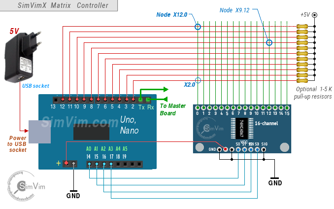
4) In case you have an irrelevant action of key nodes as (and the wiring is correct) you can add 11 pull-up resistors (1-5k) to each input line #2-12 (closer to the key matrix, not to the Arduono board!). .
Don't keep it connected to USB port after the Matrix firmware upload. Use any +5V source connected to the slave board using USB connector, or +5V pin.
Matrix Configuration
1. Click the Pin #19 in the boards table to select the slave matrix table.
2.In the Configurator: select any momentary button parameter that you want to assign and select the matrix node you need.
FMS/CDU/ MCDU predefined matrix Configuration
The SimVimX plugin has “embedded FMS/CDU” configuration for SimVimX Matrix. You won’t need to assign all those 140 buttons one-by-one, you’ll just need to select one device (Boeing CDU or Airbus MCDU) in the configurator.
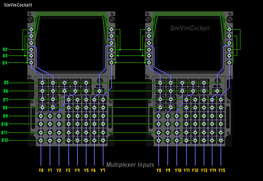
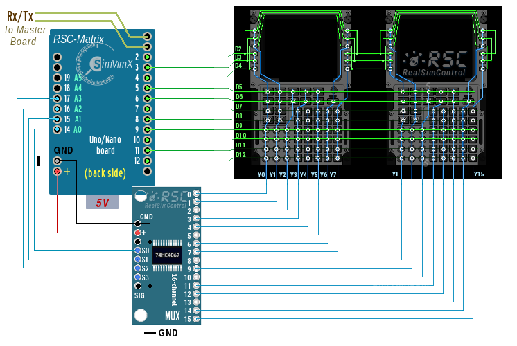
Here are the matrix wiring diagrams for two CDUs (Boeing style and Airbus style). The 16 blue columns are the multiplexer inputs and the 12 green rows are the digital pins on Arduino Nano/Uno board:
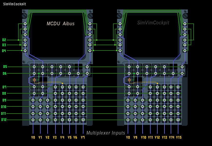
Airbus style MCDU matrix wiring is the same, except for 3 additional buttons. Note the yellow line from the Y12 column and green branch from the D6 row and additional “brightness” buttons on the Y15 column:
The standalone SimVimPanel MCDU module for Raspberry or any or mini-PC is available and can be downloaded here.