Stepper Motors Control in SimVimX
Note: here is described how to use some stepper motors with SimVimX System. For basic principles and construction of stepper motors (bipolar/unipolar), controlling types (full step, half step, etc.), you can find a lot of information in Internet.
Stepeer motors
X27.168 and similar motors are considered as main in SimVimX firmware program. These motors are suitable to replicate most of aircraft pointer instruments and can be driven with controllers, designed specifically for these very low-current motors.
28BYJ-48 (5V power) stepper motor with gearbox can be used in SimVimX with the A3967 controller in full-step mode. This motor is much slower, but cheap and easyly accessible and can be used for many aircraft pointer instruments.
Also it is possible to use other stepper motors. Be aware, though, that most of them require much more power to run, in terms of current consumption or operating voltage. Use only appropriate controllers and power supply for powerful steppers!
Stepeer Motors Control
SimVimX plugin monitors simulator parameters and translates them into signal sequences for every connected stepper motor. Firmware receives that data and converts them into specific stepping pattern for every motor, keeping track of amplitude and speed of change, simulator FPS rate and code loop timing, to eliminate jumps and ensure smooth movement.

Any stepper motor in SimVimX should only be used with a special controller (driver) that is capable to drive the selected stepper motor and must have the required output current, operating voltage, step frequency.
Be noted, that these controllers are NOT simple drivers like ULN2003, which is just a current amplifier used between the low-current microcontroller outputs and high-current motor.
Only those controller chips or boards that include STEP and DIR control inputs (also can be marked as Clock and CW/CCW) - can be used with SimVimX .
Gauge Initial Synchronization
Most aircraft gauges have a partial, sectoral dial, when the needle can only rotate in the range of less than full 360 degrees. Other important instruments have continuous 360-degree rotation (heading, navigation instruments).
To set stepper-driven instrument pointer to the start (zero) position two method can be used - either mechanical stopper or zero-position sensor. On SimVimX start or reconnection, the firmware program moves the motor shaft until the needle/card cross the position sensor or stops against the mechanical limiter, then resets position counter and moves the pointer to a position defined by simulator.
For sectoral gauge both methods are suitable, and for instrument with continuous rotation only position sensor can be used (IR optocoupler, or switch).
Limiter
X25.xx - X27.xx stepper motors have an internal mechanical limiter (stop pin), that allow you to use these steppers for any instrument with rotation up to 315 degrees without any modification.
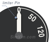
Any other stepper motors with unlimited rotation can be used for sectoral gauges, with the addition of a small pin that stops the needle rotation in the leftmost position.
Even if the motor has high torque, you can still use the stop pin for the needle. Just fix the needle to the shaft freely enough to let the shaft to continue its rotation when the needle is stopped by the pin.
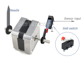
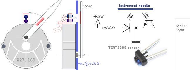
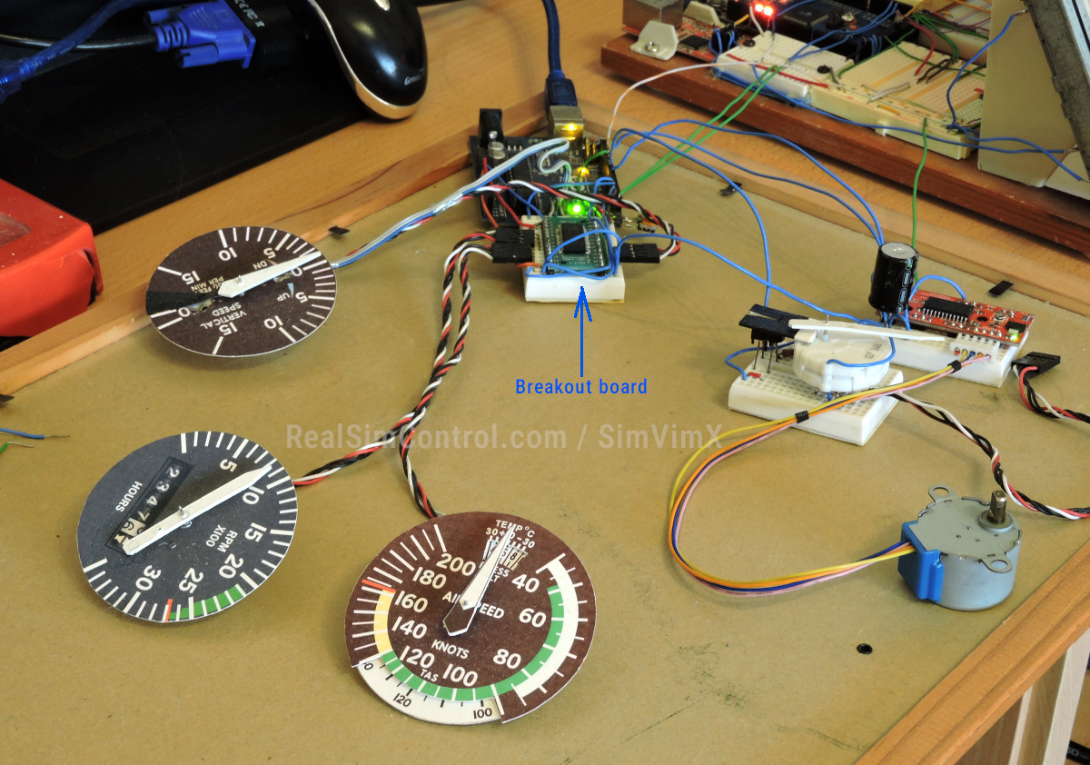
Also, for high-torque motor you can add the momentary limit switch (button) as a simple position sensor. It can be placed on the other end of the stepper motor shaft, as it's shown in the right picture
IR Positioning Sensor (optocouler)
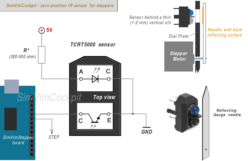
A good way to make a position sensor for X27 stepper is to use an optical (infra-red) sensor - a pair of infrared LED and IR photodiode, as shown in the picture, using the white instrument needle as the "mirror" that deflects the light from the LED onto the sensor.
As an optical pair the TCRT5000 sensor is good to use - it's simple and cheap. It should be connected as on the diagram and work fine with a resistor of about 360 Ohm (you may need to test various resistors).
Note: Place the sensor behind non-reflecting, not transparent material that has a thin (1-2 mm) vertical slit, to exclude unwanted reaction or too wide detection window. Don't make the slit it in the exact "zero" position, it may be shifted slightly CCW by half of the needle width, because it will "catch" the moment when the needle just starts to cross the sensor window.
For instruments that have no needle but have a rotating disc (card) you should paint the back side of this card black-matte. Only thin (0.5mm) white strip of paper or other good reflecting surface should be place on the back of the disc or cylinder in "zero" or "north" position.
How to Connect
Using SimVimX interface you can control stepper motors using additional "SimVim Stepper" controller board. It is simply one Uno or Nano Arduino board with special SimVimX Stepper firmware onboard (that you need to upload from the SimVimX plugin menu).
This "slave" board is connected with the Master controller board, getting data intendent for the steppers. The internal code of the slave board is fully dedicated to generate correct positioning, speed/acceleration move for multiple stepper motors.
- Every stepper motors in is connected to one of the output pin available on the slave board starting from #2.
- Namely, the "STEP" input of each stepper controller is connected to any pin you have assigned in the configurator.
- (!) If some your stepper gauge has a zero-pozitioning sensor its output should be always connected to the pin following the pin assigned for STEP signal.
- The "DIR" inputs of each stepper driver are all joined together and always should be connected to pin #13.
- Thus, you can connect up to 17-19 or (8-9 with zero sensors) stepper motors.

The "slave" controller board (Uno, Nano) is linked with the Master controller board using serial interface, when Tx output signal of one board is connected to the Rx iput of another board.
For the stepper control the Tx1,Rx1 ports are used in SimVimX . So, you should always connect the Tx pin (#1) of the slave board with Rx1 pin (#19) of the master board, and "slave" Rx (pin 0) - with the "master" Tx1 (pin #18).

Note 1. Never forget to connect the GNDs of each board ( and other devices as well) to the common GND wire.
Note 2: When you need to upload stepper control firmware to the slave board you need to disconnect the Rx,Tx wires before uploading! To simplify this you simply can add a "shut-off" switch breaking this two wires.
Another option - you can leave the Rx/Tx connected, but press the Reset button on the master board and hold it while uploading stepper firmware to the slave board.
The slave board receives all data from the master controller board only. So, you don't need to keep it connected to USB port after the SimVimX Stepper firmware upload. You can use any +5V source connected to the slave board using USB connector, or +5V pin. It can be the same source that is used for feeding the stepper motor controllers (AX1201728SG or VID6606, STI6608).
Stepper gauges Configuration interface
Choose a parameter for stepper output in the configurator and select the stepper controller output number for it. If your gauge has an initial position sensor, mark the "Position Sensor" checkbox when configuring it (for 360-degree rotation gauges it is set as default).
Options
Any stepper gauge can be "linked" with any electric bus and make it work dependant on this bus voltage. For example you gauge may stop working (and be moved to the zero position) if the bus voltage drops below assigned value.
You can assign two parameters for output to one particular stepper gauge and make it dependant on some input (switch) state or specific parameter value. For example you gauge may show voltage from different sources.
Calibration
Before using the "sectoral" stepper driven instrument in the cockpit you need to calibrate it. Use the convenient Calibration Tool in the SimVimX plugin to correctly map the data value range on the gauge dial.
! No calibration is needed for continuous (full-circle) rotation instrument. Just assign it and start your plane!
Stepper motor driven instruments, demo
Low-power X25.xx - X29.xx stepper motors
No doubt, one of the best choices for replicating most of aircraft panel instruments is using small bipolar stepper motors X27.168 (or X25, VID29 and other similar ones) that are used in car and motorcycles dashboards nowdays. You can get these steppers for a price of $3..5 a piece on Ebay, AliExpress, etc.
Instruments with limited rotation
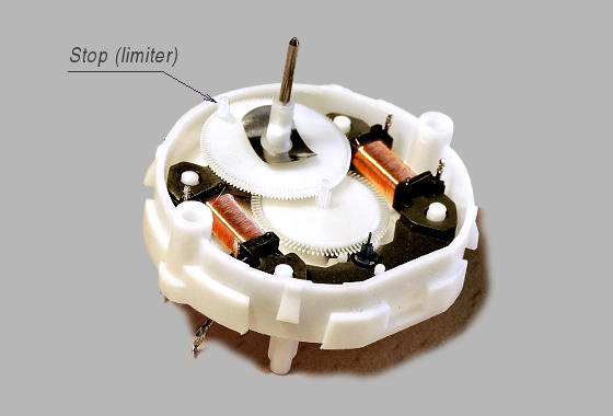
X25.xx - X27.xx stepper motors have an internal mechanical stop (see the picture below) that limits shaft rotation to 315 degrees. For most instruments with an arrow rotation angle less than 320 degrees you can use these stepper motors without any modification - no need to make zero-position sensor (though you can).
In this case, when SimVimX is started or reconnected, the firmware program moves the motor shaft until it stops against the limiter and resets its position counter.
Instruments with a full-circle rotation
To make an instrument with continuous rotation (like compass card, altitude indicator, directional needle) you need a motor without internal limiter and thus, it should have a position sensor to define the initial needle location. It can be a thin electric contact wire or IR opto sensor.
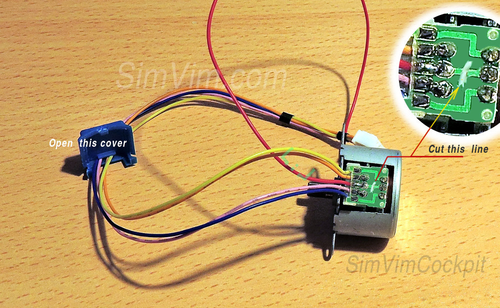
You can easily remove the stop for the Switec X27 motor, just carefully open the pair of plastic half shells of the stepper's body (they snap together without glue), and cut off the plastic stop located on the gearwheel using a sharp blade (see the picture).
In this case, when the system is started or reconnected, the firmware program moves the motor shaft until the needle/card cross the position sensor and resets its position counter.
IR Positioning Sensor
The optical pair is placed behind the faceplate at a distance of about 3..5 mm and the faceplate has a thin (1-2 mm) vertical slit in front of it.
Stepper Control
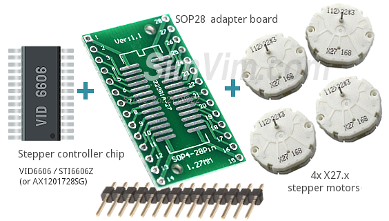
To control these very low-power motors (which draw about 20 mA only), you need to use the driver chips which are specially designed for such motors:
VID6606, STI6606Z, AX1201728SG or STI6608 chips
One such controller chip includes 4 low-current drivers and provide very precise positioning - 12 micro-steps per degree for 4 stepper motors (the STI6608 controls 2 motors).
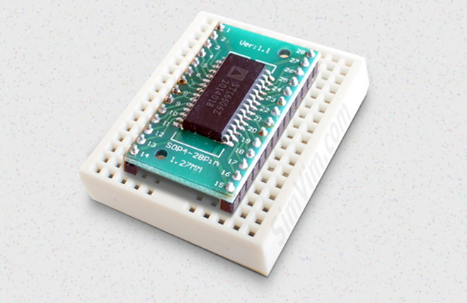
These controllers can be found online for $1 ... $2 for the chip (check the links above). Also, along with driver chips, I recommend you to buy very useful small adapter boards (for $0.1 for a piece) that will allow you to make an excellent breakout board without need to order or make PCB, and save your time and money.
Using a small soldering iron you will make a good "breakout board" for 4 stepper motors just in a few minutes and spending $2 (chip + board + header strip). If you want, you can make PCB (below is the sample of a possible one-side PCB design), but this is absolutely not necessary with technique desctibed above.
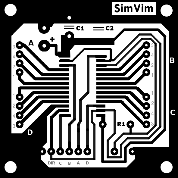
All 4 Switec stepper motors should be connected directly to the controller outputs, without using additional diodes or resistors, as shown in the connection diagram for VID6606 below. Pay attention to the steppers pin numbering.

X27.xx Stepper Control using A3769 driver
You can use these low current motors with other controllers, but be careful. For example with A3769 you can try to use the X27.xx motors, setting the driver to quarter step configuration.
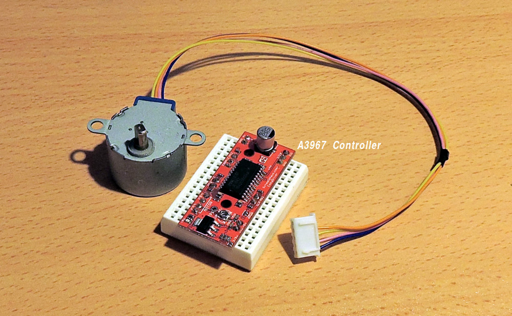
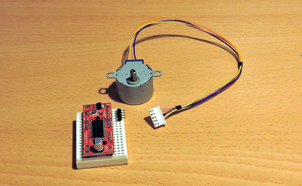
28BYJ-48 (5V power) stepper motor with gearbox
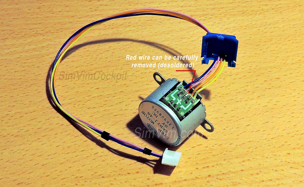
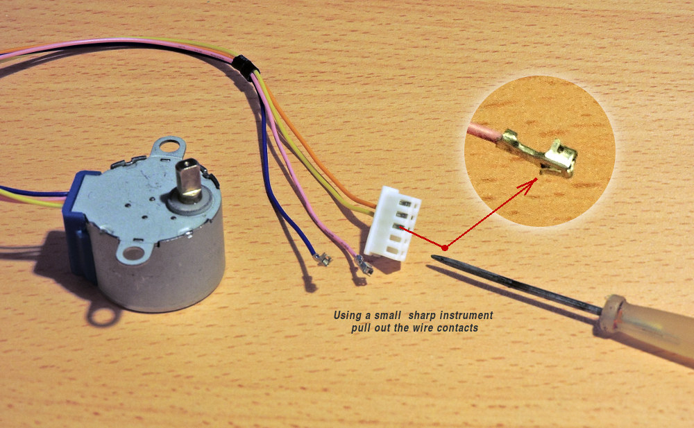
This is a stepper motor widely used in various hobby constructions, and you can use it with SimVimX too for some instruments. It's an unipolar motor but it can be easily converted into bipolar to work with controllers that drive bipolar stepper motors.
Speed
Note that this motor can be used for those gauges/mechanisms that take about 4-5 seconds to rotate 360 degrees. This motor requires a minimum lapse between steps of about 1.8 milliseconds (without load). In SimVim firmware it is set to 2.4 ms to guarantee stable work. This time is needed to prevent the motor from getting stuck when momentary data value changes too fast, causing the stepper to skip several steps, desync and stop moving.
In full step mode 360 degree rotation for this stepper takes 2048 steps, that gives you 5 seconds per rotation (12 rpm ) at the maximum speed. This is quite enough for many aviation instruments. And don't worry if some data will momentary change rapidly sometimes - the stepper firmware will not loose steps and all you can notice in this case is that the gauge needle may have some lag in movement.
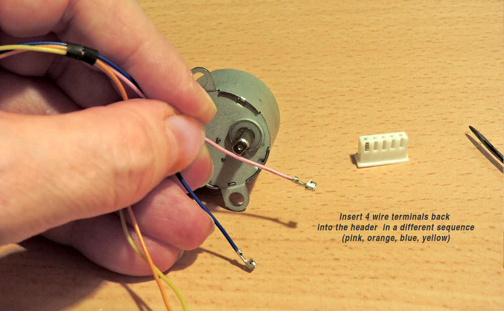
Convert to bipolar
Voltage
The motor is rated at 5V and you should not overpower it. You need to power it (using the M+ input) by an exact +5V supply, no more! Not because it can be burnt, but because if using this motor with the A3967 controller and voltage of 6+ volts the stepper will skip steps and loose precision.
Always use a dedicated external power supply, don't use the +5V output from the Arduino board!
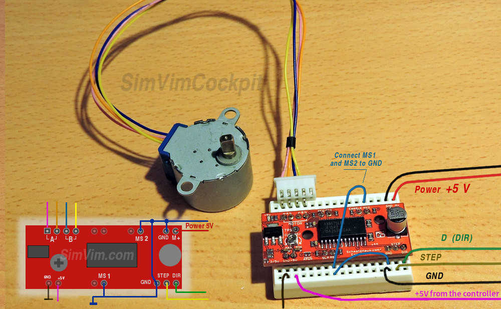
To work in SimVimX you should drive this stepper in full steps mode (the fastest mode and high torque). For this you need to set the controller you use to drive the 28BYJ-48 stepper motor in the "full-step" mode. For the EasyDriver board (or similar boards designed around the A3967 chip) you need to short both MS1 and MS2 step mode inputs to the GND.
Start Position Sensor
To synchronize your gauge with the simulator, using a start-position sensor for 28BYJ-28 motor is required. As this motor has high-ratio gear, and thus, high torque, you cannot use a mechanical stopper as a limiter ( if the needle is firmly fastened on the shaft *). Only some end-switch or optical IR sensor can be used.
(*) Actually, you can use a mechanical limiter too, if you fix the needle on the motor shaft firmly enough for normal work, but loose enough to rotate (slip) on the shaft when it is stopped by the limiter.
The end-stop switch can be used for sectoral gauges, and IR sensor - for both full-circle and sectoral instruments.
Note: When you have no sensor (or no working sensor), on reload the stepper will rotate CCW by 360 degrees, after that it goes to the position defined by the current value. Of course, it will be in different positions after each reload, due to lacking a working sensor.