How to make a cheap Breakout Board
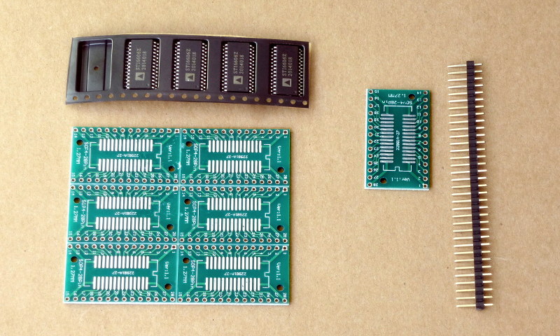
When you have to use small SMD (surface-mount) chips and there are no ready to use breakout boards, you can easily make them yourself, quickly and cheaply, without the need to make or order PCBs for each device.
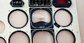
All you need is to buy cheap blank PCB boards for such SMD chips (10 boards will cost you about $1), and have very basic soldering skills to install the chip on this adapter board.
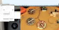
Here is an example of using this board for STI6606Z stepper driver chip. We've a got very convenient 4-stepper module for less than $2:


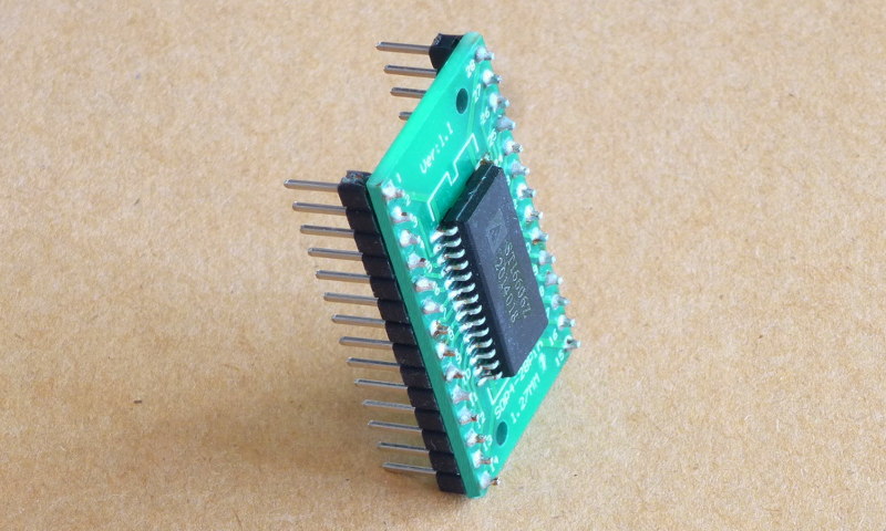
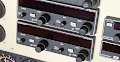
For connections you can use pin headers, socket headers, 4-contact jacks for steppers, or you can simply solder wires to the board pads directly (the most reliable connection).
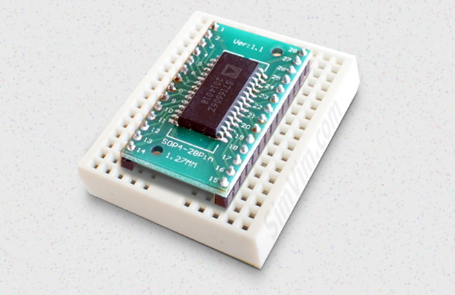
Here, two 14-pin headers were used with this module to insert it into a small breadboard. You can even place these small breadboards in your cockpit - they have peel-and-stick adhesive backing (or can have two mounting holes for screws).

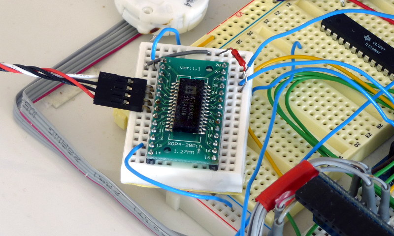
When using this board for stepper motor drivers I highly would recommend you to solder all 4 wires from each of 4 motors directly to the board pads, not using any connectors. This will be the most reliable connection for your stepper gauges.
Another 4 wires you can solder to the control (STEP) pads an make a 4-contact header to connect with the stepper controller board. Dont forget about GND and power (+5v) and common DOR signal.
More information and video can be published here eventually.