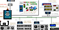
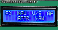
SimVimX has native support of commonly used character LCDs with 4-bit parallel interface, such as 16x2, 16x4, 20x2, 24x2 and 40x2. No libraries are used, SimVimX firmaware controls the LCD directly.
All standard ASCII Characters and a some of custom symbols can be used to display information on LCDs. Using online SimVimX configurator you can easily assign any data to be displayed:
Select any parameter to display its value at any selected position of your LCD.
You can add any "static" text before or after the value.
Any "custom" static text ("Display_Text") can also be assigned independantly to any display position.
Depending on the device selection in the configurator - SimVimX plugin can check other parameters or switch states and change displayed information conditionally.
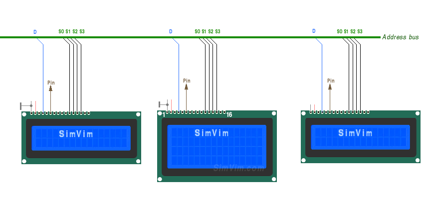
1) "Direct" connection method:
Note: We left the option of connecting the LCD display to the master board directly via the data bus. You can use any pins numbered 20 or higher. But, as most of pins can be used for input multiplexers and LED drivers, you can have up to 12 LCDs on the SimVim LCD slave board.
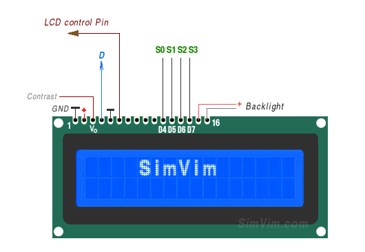
You need to use only 5 signal lines and GND connected to the data bus and one signal line connected to the output pin assigned for this particular display (only pins with numbers 20,21 and 30-53 can be used!). Four address/data lines S0,S1,S2,S3 should be connected to 4 data inputs of every LCD - D4,D5,D6,D7. The "D" signal of the bus is connected to the "RS" (register select) input of the LCD.
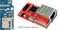
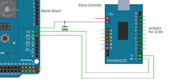
2) SimVimLCD controller on the slave board
The SimVimX firmware for a separate slave board is included to the system as addition to old method (connecting displays to master board). You need one Uno/Nano Arduino board with special SimVimLCD firmware onboard, that you should upload from the SimVimX plugin menu.
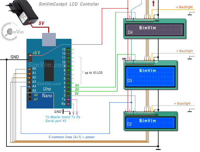
Separate, "slave" Uno or Nano board with "SimVimLCD" firmware for connecting up to 11 different size (L x H) character LCDs.
The board can be placed near to your LCD "stack" and linked with master board with 2-wire Serial interface (Rx/Tx #3 on the mastr board is used for communication).
This allows to leave the master board bus for multiplexers addressing only, get more stable data flow for LCD, more control and configuration. Some pins on this LCD board are used as "power bus" to control LCDs backlight on/off on power loss or brightness
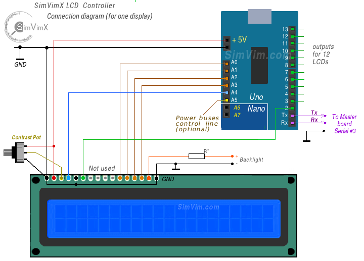
The wiring is quite simple - all signal wires (4+1) in this system are used in parallel for all connected displays, only one signal line for each display is used separatelly for every specific display.
LCD Configuration interface
Select the LCD slave board in the configurator right table, click on the free pin and assign needed LCD type.
Choose a parameter for LCD output in the configurator, then select an assigned display number and enter the line number and position for your data.
To output additional parameter value on the same display, you need to select second parameter, then select the same display output pin number, add parameter ("New Entry"), and then enter start position and line number.
Options
You can configure LCD to display some custom text with the data value or as fixed text or text displayed by conditions.
You can select a "LED-type" parameter (annunciator) and configure it for LCD to display some custom text as annunciator.
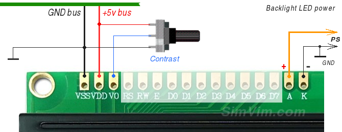
LCD Powering
These displays don't consume much power, so you can use +5v from the slave board. To be able to see something on the screen, you need to add contrast control to the input (V0) using a small potentiometer / trimpot (resistance can be from 1K to 10K Ohm) connected between +5V and GND:
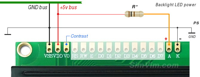
On the other side of the LCD there are two inputs for the backlight LED ( +A - anode, -K - cathode). The "K" input connected to the common GND, and "A" - to the "+" of the power source, which can also be an additional power supply.
Although the backlight LEDs can consume quite much power, you can still connect the A input to the bus +5V instead of an external source. This is especially viable if you use a powerful source for +5v line in your system bus, not taken from the controller board +5 output. Use an additional resistor (50 - 100 Ohm) on the A input in this case.
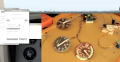
Video: Test with 3 LCD ( 40x2, 16x4 LCD and one 20x20 OLED display):