ON/OFF Position Indication for Switches
The appropriate SimVimX parameter must be assigned and the LED wired to the RSC input when it is used to indicate a system state (system on, off, failures), not just a switch position.
But, there are a number of lamps in a real plane cockpit that only indicate the ON or OFF switch position, not a system state, especially when it is a push-button switch (korry-type), the mechanical positions of which are not easy to distinguish.
That means that not every LED on your panels needs to be assigned as a SimVimX parameter and wired to the controller.
You can see that your virtual plane model has a specific dataref for each lamp in your virtual model because the plane model developer must use the datarefs in the X-Plane for each indicator and each switch to associate the corresponding graphic / animation elements with them for visual presentation on the virtual panel.
To indicate a switch position (on/off states) without assigning parameters and spending digital inputs, you may simply solder the LED to the switch terminals using one of the options below.
1. DPDT switch
Using toggle switches (including Korry-type switches) with more than one "pole" terminal (DPST or DPDT) allows you to use the first contact group for the input signal control, and the second group for LEDs on/off control.
To indicate the switch ON position the LED should be connected to the NO (normally opened) terminal. For OFF position indication connect the LED to the NC (normally closed) terminal:

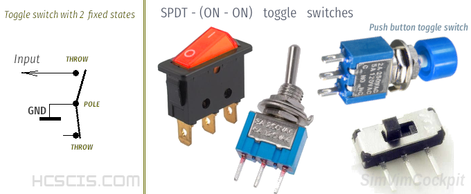
But if you have a single-pole (SPST, SPDT) switch, you can still use a LED to indicate its current position when using it with RealSimControl . All possible options are described below.
2. SPST switch
The simplest toggle switch has only two terminals - one "Pole" and one "Throw", this is the SPST toggle switch type that has two fixed (maintained OFF-ON) states. There is no difference between pole and Throw for such switch in terms of electrical connection (you can connect it either way).


For this switch type you can easily implement the "ON" status indication. To do this, you need to connect the LED's cathode to the same terminal that is used as the input signal, and the anode must be connected to the +5 bus with the appropriate resistor in series. The value of the resistor should be chosen based on the LED brightness that you want to get, but preferably not less than 1 kOhm.
From my experience, even if you use a resistor of 2-3 kOhm the LED brightness is quite enough to indicate that the switch is ON.
As all inputs are configured in RealSimControl firmware as default high-level state with pull-up resistors, connecting a LED this way will not affect the digital inputs in any way. Throwing the switch will short the circuit to the ground, activating both the input and the LED connected to it.
3. SPDT ON-ON switch
Toggle switches with 3 terminals are very common - one "Pole" and two "Throw", this is the SPDT toggle switch type that also has two fixed states (ON-ON), but connects one input terminal (pole) to one of two output terminals. No matter if you use only one output circuit or both, you need to know where the pole terminal is located.

For this switch type you can implement the "OFF" status indication by using the second signal line. You need to connect the LED's cathode to the terminal that is NOT used as the input signal, and the anode to the +5 bus with the appropriate resistor in series.
The difference from the SPST switch is that you can use any resistor value that you need for your LED brightness, and you can even use any VLED voltage to power the LED, because in this case it doesn't interfere with the signal line.
At the same time, you can still use the signal side for the ON state indication LED as described for the SPST switch above. Or, you can use both position LEDs as shown in the picture below. Note that the two LEDs used here are powered from +5V and have a single resistor (only one LED can be powered at the same time). As an option you can use two power lines and two resistors.

4. SPDT ON-OFF-ON switch
A 3-position toggle switch that also has 3 terminals is the same as SPDT switch, but it has one more fixed position in the center (OFF). It can be called a Single pole, centre off (SPCO) switch. So, it has 3 fixed positions (ON-OFF-ON) and is used like two separate switches that aren't supposed to be ON at the same time.
For this switch type you can make the indication for both "ON1" and "ON2" position using the signal lines. You need to connect the LED's cathode to the same terminal that is used as the input signal, and the anode must be connected to the +5 bus with the appropriate resistor in series. Again, the resistor value is chosen based on the LED brightness required, and preferably not less than 1 kOhm.


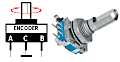
5. Rotary Switch with a single group of position terminals
A multi-position rotary switch (here is an example with 5 positions) that has only one pole and only one group of 5 Throw is used like 5 separate SPST switches that can not be in the ON state at the same time.
Connect the LED's cathode to the same terminals that is used as the input signals, and all the LEDs anode must be connected to the +5 bus with one resistor in series. The value of the resistor should be chosen based on needed LED brightness as described above for SPST switch.
.
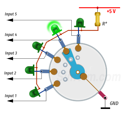
NOTE: of course if your rotary switch has the second group of output terminals (another 5 Throw, the pole can still be single) you should use them for LEDs power commutating..