WIRING GUIDE
The home cockpit wiring (in relation to Input/Output control interface as SimVimX )
is a data transfer system,
this is not "electrical" wiring that works with AC/DC voltage supplies to provide power to various consuming devices.
So, you will never need to use those 10-14-gauge and even 20-gauge wires and thick stranded wires (see below) that are used in electrical AC/DC power lines for high current/voltage power transmition.
For such systems as SimVimX interface, the signal wires length doesn't matter in terms of your whole cockpit dimentions (where even wire length 1.5-meter is barely possible). It's a digital low-frequency system with strict logic level signals, every single wire (line) transfers specific data sequence in specific moment or period of time. The "digital logic" signal wires are not power transmitting lines and the current in these wires is extremely low - usually it's just a few microamperes.
The logic data sequence is a group of short pulses of logical level (high/low, or 0/1), when low level is 0 volts and high level is about 5v (or 3v for some chips). There is no intermediate levels in logical signal lines, it can be only 0 or 1. This is guarantee that a device will always receive uncorrupted data, even if it is connected with the data source using long and very thin wires or you have quite a noisy electrical environment:

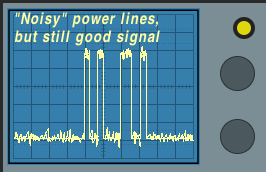
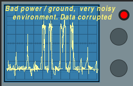
You can use very thin wires (30-35-gauge), the wires thickness and length does not affect the "quality" of the signal in these lines, only "environmental" electric noise can influence the signal in certain conditions - bad power, interfernce, "messy" and "loopy" wiring in combination with long wires.
Wire types, AWG
Eventually it's up to you, but I would highly recommend to use thin, solid-core (not stranded) wires for all connections in your cockpit to make "clean", neat wiring.
By "thin" wire I mean about 30 AWG (or 0.25 mm) core. I always prefer to use solid-core wire. It's very comfortable to use, it can be easily wrapped around other contact legs. This "wire wrap" connection can be used by itself and can provide quite reliable joint for some connections, especially if you use some wrapping tool, but in some cases you would better solder the joint for more solid connection.


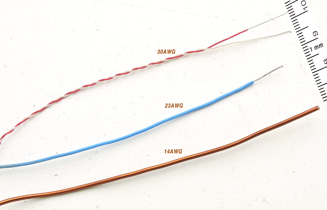

As for rumors :) that the solid-core wire is "non-flexibile" and "brittle", it's not true. A thin solid-core wire can be bent easily to any angle, and not just once, of course. It keeps the shape that allows you to comfortably lay the wire on any surfaces fixing it with small drops of thermo glue. Using these wires in the overhead panel, for example, makes it all very clean and accessible - all your switches will not be buried behind wiring.
Other solid-core wires that can be used:
- 22-24 AWG, good for mini breadboard connections, local ground wires.
- 12-20 AWG, uncovered copper wire for GND bus. Also all metal panel surfaces (connected together with GND bus) in your cockpit can be used as common ground.
For the reference here is the link to the AWG specification table: American wire gauge.
Topology
Often in some cockpit photos you can see bundles of very thick stranded wires ( even 1 mm in diameter )- this looks very messy and can lead to unrealible work.
On the other hand, clean minimalistic wiring guaratees your system will work smoothly.
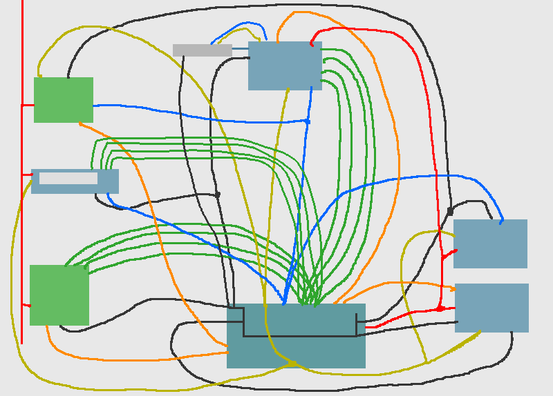


I affirm that in all cases, when someone reported about LCD "garbage on screen", "not working 7-segment display" issues, eventually the cause always been some bad contacts in headers, poor soldering, messy wiring, or noisy weak power lines.
Follow these few rules:
- Don't use tick wires, it's absolutely useless, they only fill too much space.
- Don't allow wires to be of excessive length, crossed up with other wires, this may create many loops, sensitive to interference.
- Don't use many excessive, unnecessary wires, particularly many "common ground" wires, forming parasitic current loops, leading to unstable work of some devices.
- If you can barely see the components between all of the wires connected to these components - it's very bad wiring.
- If you can barely notice all the wires that are connecting all your devices and it looks "neat and pleasing" - it's good, clean wiring.
- Cut excessive wire pieces, keep every wire length exactly the same as the distance between devices.
- Lay all thin wires in one level along a flat surface (can be glued, taped, etc.)
- Combine several thin wires into one bunch, in case of 4 address lines it will be almost unnoticable on your panel when using 30-gauge wires.
- Avoud to use many connectors along the wiring path, use minimum of connectors only where it's necessary or unavoidable.
- Use the soldering everywhere when possible, or wrapping / screws.
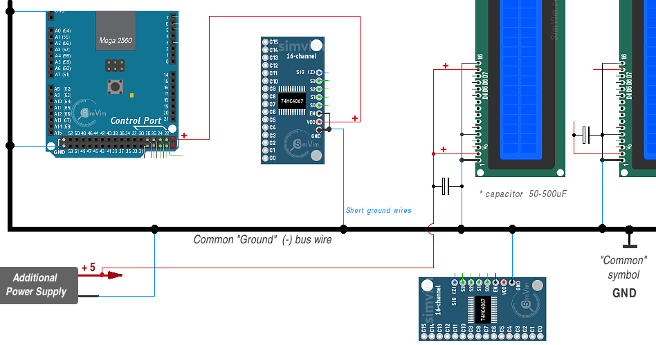
I often mention it - when you are building you own home cockpit, you don't need to use a lot of connectors, detachable modules, etc. Only few necessary connectors are needed and all thin wires can be laid (attached to flat surfaces everywhere) neatly across all panels, the thin address bus wire bunch can be going from one panel/device to another (in chain), one GND bus wire layd along all panels as thick copper wire.

Common Ground Wire
GND is a common bus, that can be just a thick single-core wire (from 16 AWG to 8 AWG)
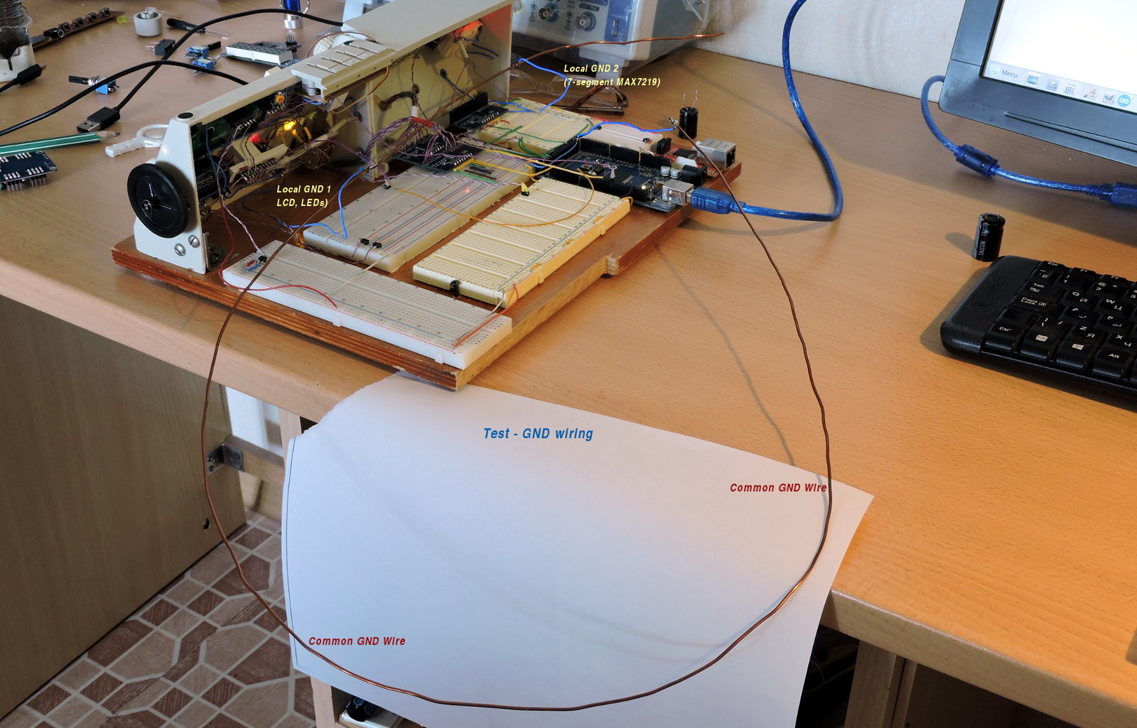
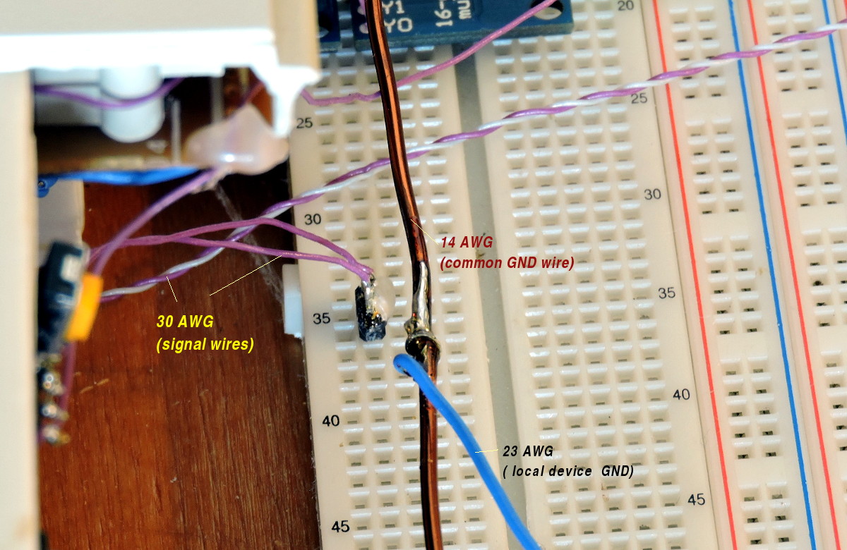
In the test setup on these photos I have used the 16AWG copper varnished wire (the varnish is removed before soldering in join spots.)
To avoid ground current loop effects and ambient electromagnetic induction, you need to follow some basic rules. As example here is the wrong and right connection options for 7-segment MAX7219 displays:
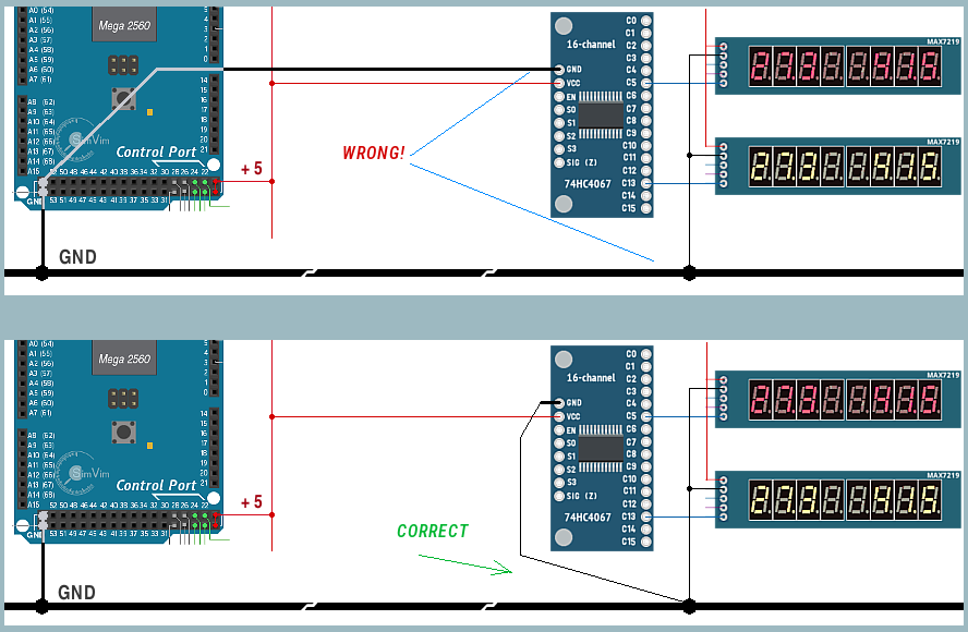
If you have some unpredictable On-Off LED states or corrupted display data, please use correct ground wiring, additional pull-down resistors for displays, pull-up resistors for input multiplexer boards and additional electrolytic capacitors, as described on related hardware pages.
PCB or "direct" wiring
That's a question: Do we need to make (order) any PCBs in our home cockpit?
My simple answer - no. Personally, I prefer not to make any PCBs for such simple and stationary projects as home cockpit, although, as electronics specialist, I made a lot of PCBs in my life.
It's all up to you, only you choose how to wire your whole cockpit or parts of your self-made cockpit panels. Of course, today you can order any PCB online for price of $1-5. But, why would it need to be used at all?
First of all, I strongly discourage the use of any kind of "integrating (master)" PCB in such a bus-organized system as SimVimX with widely dispersed work area as a home cockpit.
1. For any panel, small or big, which consists of switches, buttons, encoders and LEDs, making a PCB is a useless and excessive. All these swithes, LEDs already are installed in the plastic or metal panel and all you need is simply wire them all with a few inches of wires . I think nobody make a PCBs for such panels.
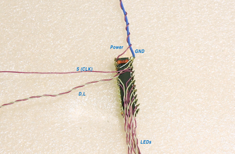
2. The MAX7219, TM1637 and LCD display modules are small PCB itself. They also simply can be fixed on any plastic panel, and wires can be directly soldered to their contac pads or wrapped around ther pins.
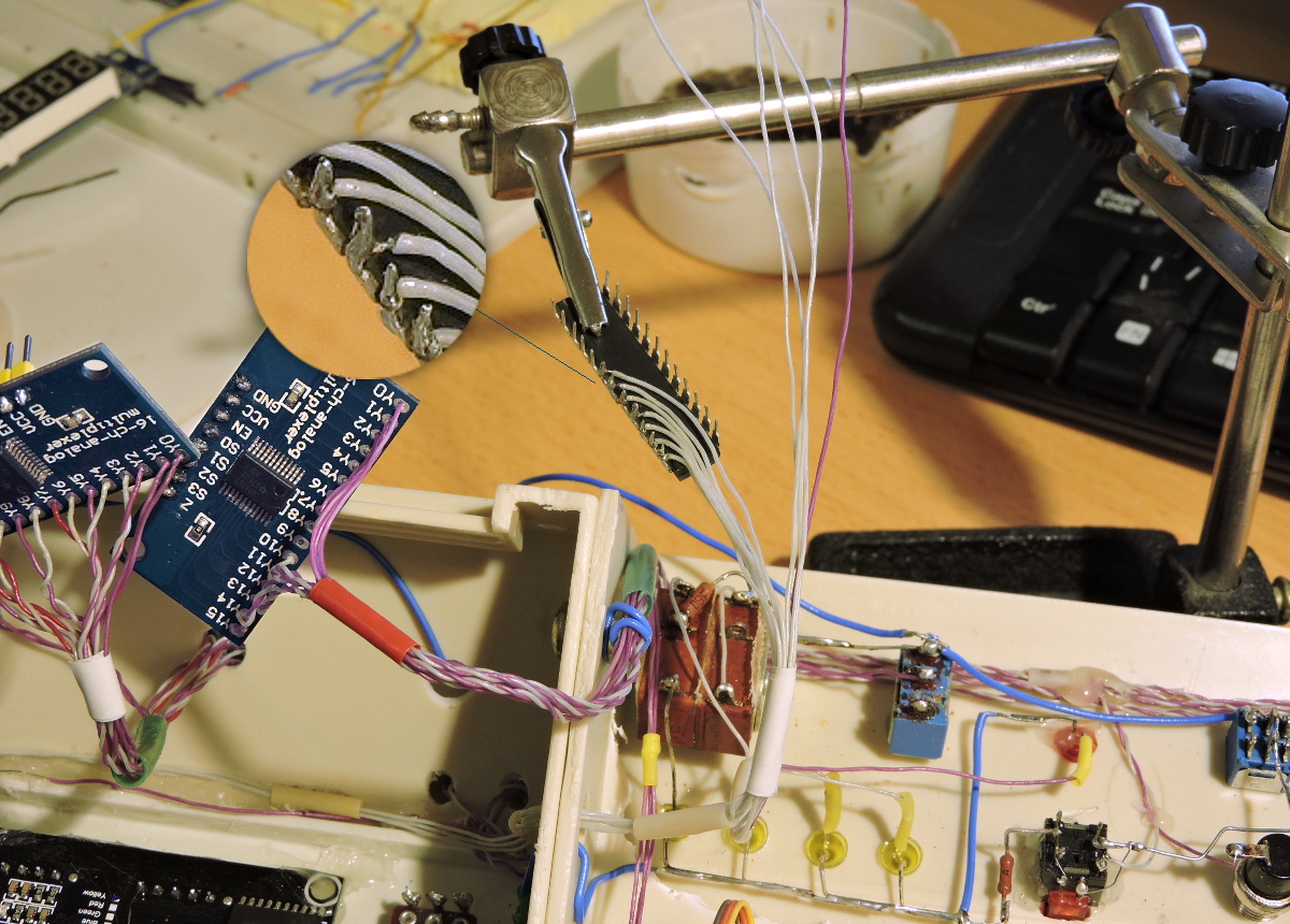
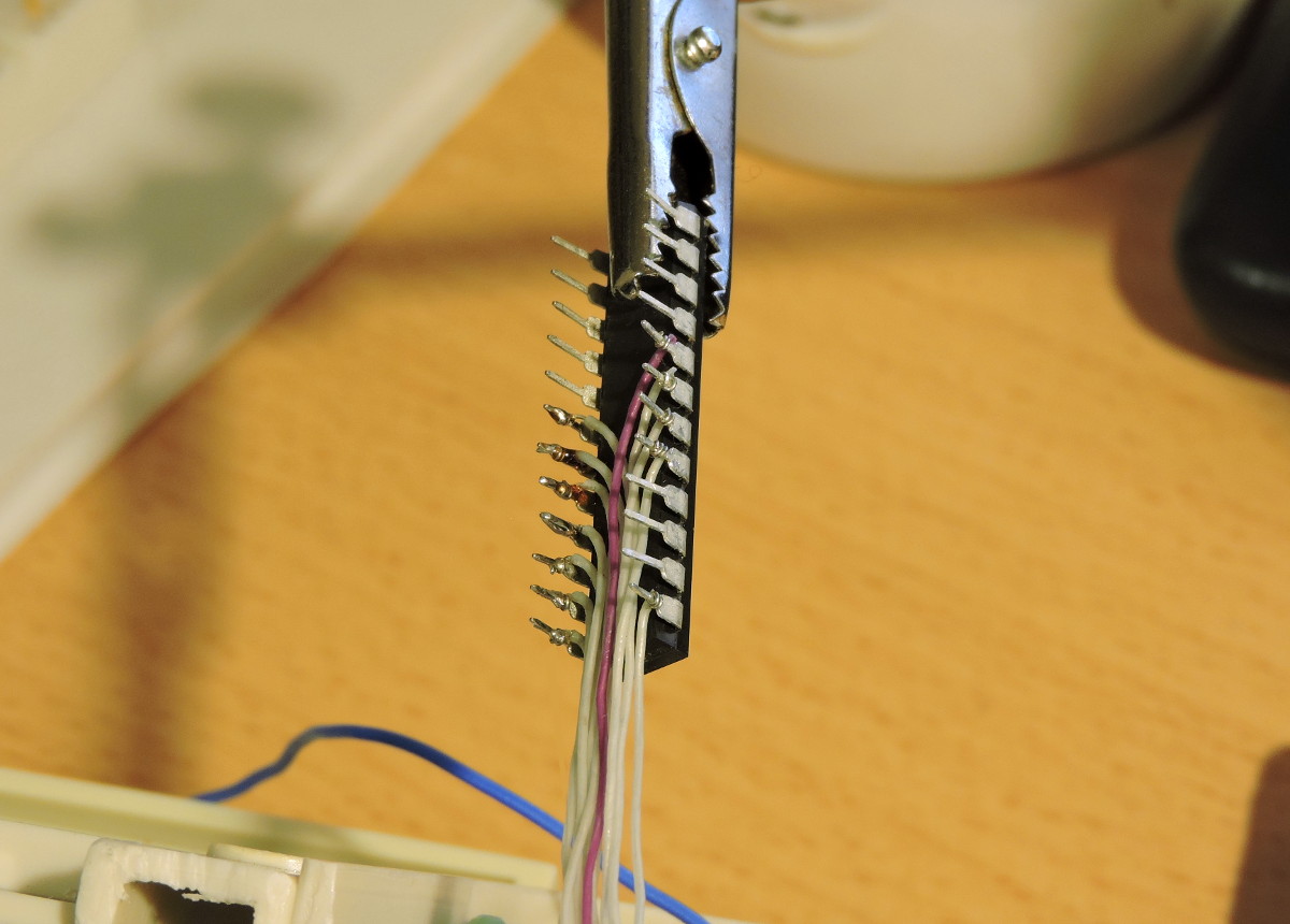
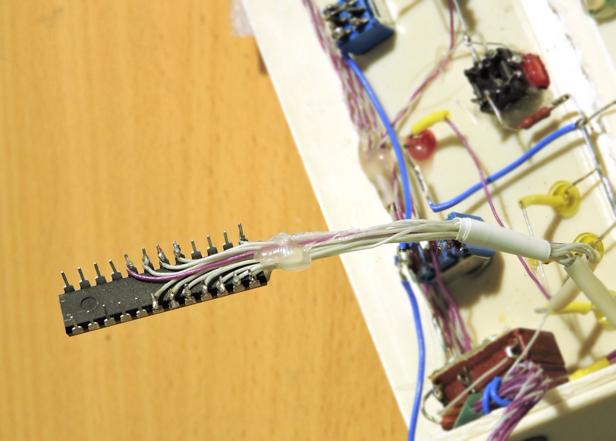
"PCB-free" chips soldering
It's obvious for two examples above you don't need PCBs. But if you need to use a bare chips for 7-segment indicators or LEDs, you don't necessary need PCBs too.
As example, using DM13A drivers in DIP casing, you can solder thin wires directly to the driver pins. Then this driver can be attached to the surface near the LED group using thermo-glue or 2-side duct tape.
First, the thin (30AWG) solid-core wire is wrapped around the chip pins with tweezers or with a special wire wrapping tool.
After that touch every joint with solder and melt it quickly with fully heated soldering iron, making the melted solder leak into the joint spacing for a reliable connection: