Master Controller board and Peripherals Powering
If you have just started to work with electronics, you may have trouble making your setup work. The cause of some problems can be improper powering, grounding and wiring.
Sometimes, devices powered from the controller (Arduino) drain too much power for it to handle, sometimes incorrect pins are used for powering. At best, some output devices don't work until the problem is fixed. Worst case - the controller may be permanently damaged.
Controller board (Arduino) powering
The controller boards (Arduino and other mega2560 boards) include power inputs (at least one) and outputs for use as power sources for other external devices:

Powering options:
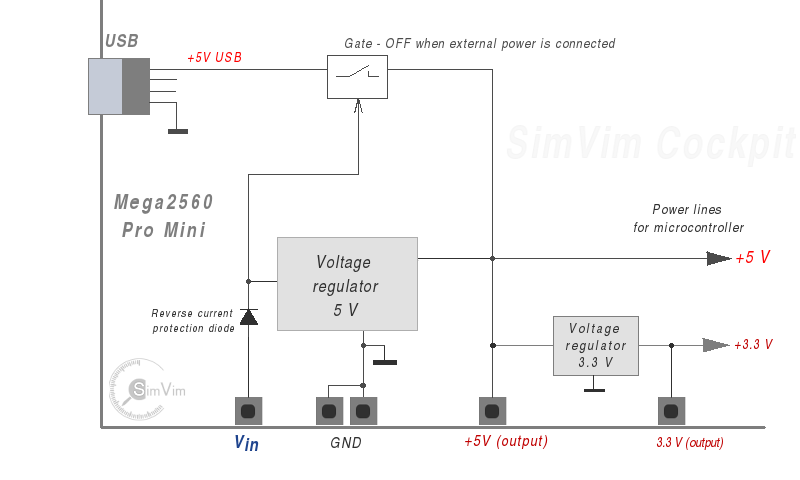
- 1. USB connector (5V). It can be a USB cable from the computer or a stabilized 5v power supply with USB connector (only when USB inteface is not used).
- 2. DC power jack with external power supply (7...9V), or Vin pin for external source (see some notes below).
The 5V and 3.3V pins located on the board header can be used only as sources (output) for your peripheral devices (if their total power consumption does not exeed 300-400 mA in case of external power supply, see the notes below).
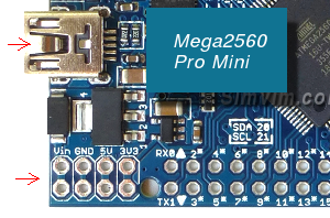
Vin header pin can be used for external power source (if you can't utilize the power jack for some reason), but be warned that Arduino has no reverse-voltage protection diode on this input. If you connect it wrong you may permanently damage your board. However, the Mega Pro (mini) controller boards have this protection (these boards have no barell jack).
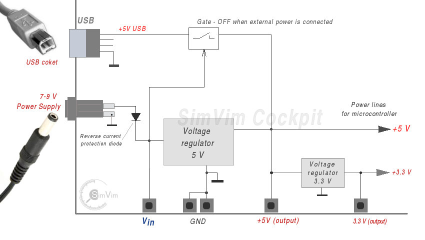
NOTE: If you cannot power your board through USB (5V) or power jack/Vin (7...9V supply), you can connect external +5V power source to the header pin +5V to power your board, but you need to be sure it is a reliable stabilized source of +5V and never exceeds 6V! You can use it only when USB power is disconnected and no power supply is connected to the DC barrel jack!
The computer USB2 port supplies 5V, 500 mA stabilized power, which is quite enough to supply the board, all multiplexers and several low-current devices.
If a DC power source (7-9V) is connected to the Vin pin or to the barrel jack, the power line from the USB cable is disconnected from the internal 5V bus (the analog gate is closed by voltage comparator, see the pictures above).
Using the +5V header output as a power source for electronic components
As mentioned earlier, the 5V and 3.3V pins located on the board header can be used only as sources (output) for your peripheral devices (if their total power consumption does not exeed power source limits, see the notes below).
When Power Supply is used
First, in most cases you never need to use this power jack, the USB power is quite enough to feed your board and several devices. Read the details below in "When USB Power is used".
Second, it's pointless to use a high-power source to feed the Mega2560 board through the power jack and additional devices through the +5V output pin. Why?
The maximum current for voltage regulator used in Arduino is 1 A. But you cannot allow the +5 output to be loaded with such high current!. The regulator has a maximum power dissipation rating that cannot be exceeded and it doesn't have a massive heatsink.
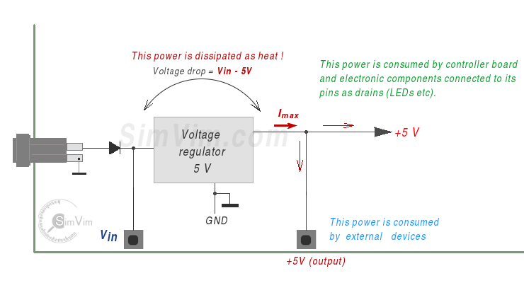
When you use power supply 12V to down it to 5V the regulator itself should dissipate much of the excessive power. That means that 7V out of 12 are "wasted" and need to be dissipated as thermal power (12 - 5 = 7) and with load of 1A you'll get 7W which is huge power to dissipate as heat.
Even with the load no more than 300 mA the regulator may be quickly overheated without using a heatsink, because it will need to dissipate 2 Watts of power (7 x 0.3).
With input of 9V you can load your +5V output with more current (about 400-500 mA) without overheating and using heatsink.
That's why it's useless to connect a high-power source to the power jack, even if it's rated as 2A source you can utilize only about 400 mA, the same 400-500 mA you can get from the computer USB power.
You need to have a good, stable power source that doesn't have much higher voltage than the 5v you need to get. But there is a minimum limit for input voltage - to get stable output with this type of linear regulator the input voltage should be at least 1.5-2 V above the desired output voltage. So, you need to have at least 6.5 V on input, the optimal is 7-9 V, 300-500 mA.
When the computer USB Power is used
1) If you don't use the Arduino output header (5V) as power source for any other devices in your system, you only need USB power, nothing more!
2) If you use the output header (5V) as power source for current-consuming devices, and their total current doesn't exceed 400-500 mA, you may have just the USB power, too.
When Power supply with USB Power socket is used
This option can be useful when you use SimVimX Ethernet version. Using the USB socket, you can connect any 5V power supply, with any rated current. For example, if your 5V power supply is rated for 3A, you can use the +5V pin as source for devices with summary current of 3A.
Summary
When powering your output devices from the board header pin +5V you need to estimate the total current, calculate a sum of currents, when all devices consume maximum power (all LEDs are ON, all 7-segmend displays are in high-brightness state, etc.)
This summary current should not exceed the rated power supply current in case of USB !
All devices in your system need to be connected to the common GND bus wire (the symbol  is used as common ground wires for every device pictured on this website).
In general, with SimVimX you don't need to use additional power supply connected to your controller board, the power from USB cable is just enough to use +5V output pin for any number of multiplexers connected to the bus and a few other low-current devices.
Additional (separate) power supply (5V DC) should be used for powering all other devices that may consume quite much power.
Precautions when using electronic components
To reproduce all tech solutions presented here you should understand all possible risks and carefully learn all aspects of using electric and electronic equipment. Keep in mind the basic rules of connection and powering to prevent controller damage, short circuits, etc.
- Do not use external power supply for your board at all (it's pointless, see notes above).
- If an external power supply is used, it should be 7 - 9V (and 300-500 mA, see notes above).
- Use only direct current Power Supply (stabilized DC supply is preferred).
- Do not put your circuit boards on a conductive surface when power is ON.
- Do not use the +5V output pin on your controller board as source for high-power devices (see notes above).
- Keep track of your wires! Don't leave wire ends floating around freely - they can be a cause of unexpected short circuits.
- Make sure that the GND wires of all devices (and power supplies) in your system are all connected to the common GND bus wire.
- Make sure that no power lines are connected together (never connect the +5v from different sources together! )
- It's preferable to turn the power OFF before you rewire your connections.
- Don't let the pin that is configured as output be shorted to the GND, power lines shorted between each other, input pins shorted to outut pins, etc.!
And finally - keep your wiring clean!
Don't create a mess of wires, don't create multiple ground loops, don't use unnecessary, overlapping/doubling wires, etc.
Use the thin (30-26 AWG) single-core wires for signals.
Cut the wires to the minimum required length, make some groups of wires (using flexible tubing or electrical tape).
Use soldering everywhere when possible, check all headers for contact reliability and solder quality.
Read the wiring guide here.
SimVim Configuration and wiring
The usual safety measures to prevent you from burning your electronics/controller include checking if your input/output pins are correctly assigned when you have some devices connected to the master board.
Note that SimVimX configures all controller input and output pins according to the configuration file. As such, if you have some devices connected to your Arduino pins, especially if they are powered output devices, check that these pins are correctly assigned in the "data.cfg" file.
! Leaving the pin unassigned will not cause any problems, but if a pin was assigned for output and you accidentally connect a switch to this output, you can overload and burn it by connecting it to the GND.
This combined diagram was designed to provide you a convenient reference for the proper powering practices for your SimVimX setup:
