FeedBack Systems
Some home cockpit builders may decide that just having a "real" cockpit itself is not enough and they need two more things that could make their flights more realistic (at least as they may think) - the full-motion cockpit and the feedback from controls (and environment).
What do you really need, what can you do and what is really worth doing?
Cabin motion

It's quite obvious that the full motion cabin is an absolutelly unnecessary thing for a home cockpit simulator. It will lead to a very costly and lengthy building process with dubious results.
1. To get even roughly realistic motions with at least subtle gyro and G-effects, you need a lot of free space, way bigger than a room in your house, and you still won't be able to imitate the G-forces that you can feel in a real flight.

2. Leaving aside the G-effects, you may think about more simple mechanics, such as the cabin platform tilting, hmmm... maybe to better feel the plane maneuvers?... No, it also won't work...
Yes, a slightly tilting/vibrating cockpit can add some feeling of immersion (how - see below on this page).
But don't build mechanics that deeply tilt your cockpit using the virtual plane bank angles (as some cockpit builders do), it will be totally wrong because in the real flight you don't feel the tilt, even in a deep turn, so at least you should not use the simulator bank angles for this.
3. The greatest effect can be achieved visually, and having a big screen (or several screens) and a fully-closed cabin is more important, and it's more than enough to get the "immersion" effect.
Back to the "feedback motions" - the easier (and - realistic!) way to implement them are engine, turbulence and gear-on-ground cockpit vibration effects.
All this can be easily simulated in RSC/SimVimX:
- 1You may get a vibration signal from each engine and rotate disbalanced DC motors controlled by PWM and attached to your instrument panels, to your seat, etc. This is the easiest effect to implement.
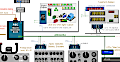
- You have 3 motion signals for vertical gear movement range (see the "Misc" tab in the Configurator). Your fully closed cabin can have 3 actuators (powerful and fast servos) under the floor platform with the stroke of about 5-10 cm (that's enough for good gear-shaking feelings).
When your plane is running up or landing, each actuator will be moved exactly according to absorber spring vertical deflection of the related landing gear.
This effect is more complex to implement, but, in a simpler way, you can simply put your cabin platform on 3 springs (see the small picture above) and allow the 3 servo motors to pull each point down with a metal cable.
- In addition, you can use 3 motion signals for X,Y,Z vibration for atmospheric tubulence. For this you need another 3 actuators with the stroke 5-10 cm to tilt, pitch and roll your cabin accordingly with the 3 tubulence forces. This effect can add a lot of realism, but it's even more complex to be implemented.
To simplify the whole constuction, the same 3 "Landing gear effect" actuators can be used also for turbulence effect, but for this we will need to write an additional "conversion" custom function (maybe later).
Note: All these effect you can easily assign in the "Feedback" section of the RealSimControl Configurator.
Controls Feedback
As for yoke feedback , in general most of such systems are unrealistic - you can find some information about attempts to make this on the Internet. Often it is just DC or stepper motors that provide forces to prevent your attempts to move the yoke, and the question is what data those motors are using.
Simple spring-centered mechanics (preferably using a rubber cord) can be more affordable and realistic than the noisy, jerky, motor-driven mechanism with unreal forces.
At least, I suppose that you don't need any "feedback" for the roll axis at all, and barely need it for the rudder. A good centering mechanism for the rubber cord (with center point that is moved by trim output signal) is fully sufficient for these two controls.
The only "real” feedback that worth trying to implement is the pitch control for GA aircraft. But what data do you need to use for this feedback, and how to provide the necessary force?
Obviously, for small GA aircraft with direct control, the main ( and sufficient! ) data source is the aircraft’s flight speed, which is the most determining source of dynamic forces for the control surfaces.
Later I plan to post some of my thoughts below on how to simulate a simple but fairly realistic force of feedback and design the yoke mechanics.
Auto-throttle control
Of course there is no essential need to complicate design and implement the moving lever mechanics in the autothrottle mode, especially if the simulator is turning the joystick (throttle) axis off in the A/T mode (as it's done in the X-Plane B737 Laminar).
(Actually it's only appropriate way to have the A/T mode with hardware input, and if the plane model doesn't ignore the hardware (hoystick) input in A/T mode, you will get constantly jumping lever in the virtual cockpit).
But you may want to have the moving levers for the visual realism or at least to eliminate the virtual lever jumping to the current position on the autothrottle disengage.
A/T implementation
The problem is that there is no special auto-throttle "target" dataref in X-Plane, specifically dataref that defines the "commanded" value (the real lever position to move ) independent of the virtual throttle position dataref.
This is how it works in the virual plane model: when the plane model is in the A/T mode its program simply changes the lever position dataref to the needed value that moves the virtual lever.
How it should work in the hardware implementation:
- - when the plane model is in the A/T mode, the plane program should NOT change the throttle dataref directly, it should have special, additional dataref for the external servo;
- - in this case the the servo is controlled by the A/T dataref, moving the lever, it's the same as you will move the throttle by hand.
As the second variant is not available in simulators, the only way is to move the servo with the throttle position dataref, but in this case the data is used for moving the input sensor that change the same data.
So, in SimVimX plugin it works this way:
- - when the A/T mode is initiated the throttle position dataref is used to define the servo position.
- - In that time, the the lever position sensor input (assigned as SimVimX parameter) is blocked by the plugin, and there is no concurrent input/output feedback loop.
- - Note: this may not work if you are using the SimVimX for the A/T servo control, but not using the SimVimX for the input and the plane model is not blocking the throttle inputs (joystick) in A/T mode.
For example, when the AT mode is enfgaged in the default Laminar B738 plane, you can move the throttle freely without affecting the virtual datarefs. In the Zibo mod B738 you need to go to the tablet hardware menu and turn ON the "A/T Engaged Lock Throttle"
To be continued...