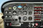
Cessna 172 - Instrument-only panel | Full Panel ->
The beta and full versions are available to subscribers on Patreon.
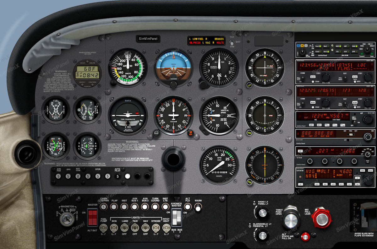
The instrument-only panel version is designed for LCD screens placed behind overlays (plastic, metal, plywood, or cardboard) containing only instrument cutouts. If you have set the correct (native) resolution for the monitor you are using and the screen sizes of the monitor are correctly read by the program, the panel is displayed as close to the real life size as possible. All instruments are correctly positioned (the distances between instruments are as close to real as possible). The default SimVim C172 panel cutout template is available below on this page (download the zip file).
But, as the cut-outs spacing can be slightly different in your panel, every instrument on the panel can be moved in the range of 5% of its default center position. Please read the panel configuration guide here.
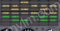
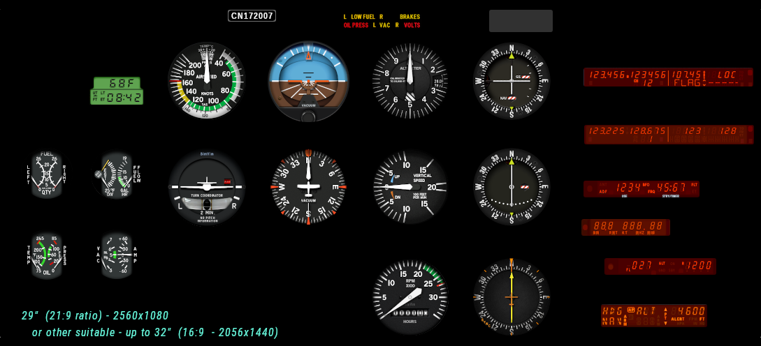
The C172 module includes 6 instrument layouts for various LCD sets.
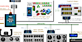
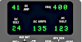
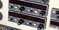
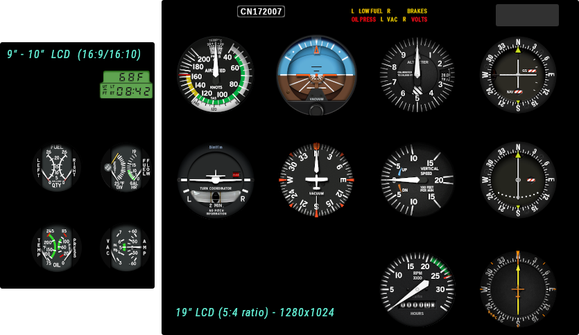
1. The full panel on two monitors - one (9-10" LCD) is used to diplay the engine gauges and clock and 23-24" screen is used for the main instruments and radios. The radio panel is included (no hardware radios are used).
2. The full panel on one large (wide) screen (29" (21:9) or any suitabe 30-32" LCD). The radio panel is included (no hardware radios are used).
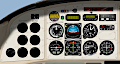
3. Two LCDs are used - one (9-10" LCD) is used to diplay the engine gauges and clock and 19" (5:4) screen is used for the main instruments. The radio panel is not included (if you have "real" hardware radios built).
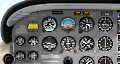
4. A single (23-24" LCD) is used to diplay all instruments. The radio panel is not included (if you have "real" hardware radios built).
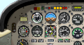
5. A single (21.5-22" LCD) is used to diplay all instruments but without annunciators. The radios and annunciators are not included (if you have "real" hardware radios and annunciator panel built).
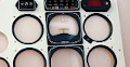
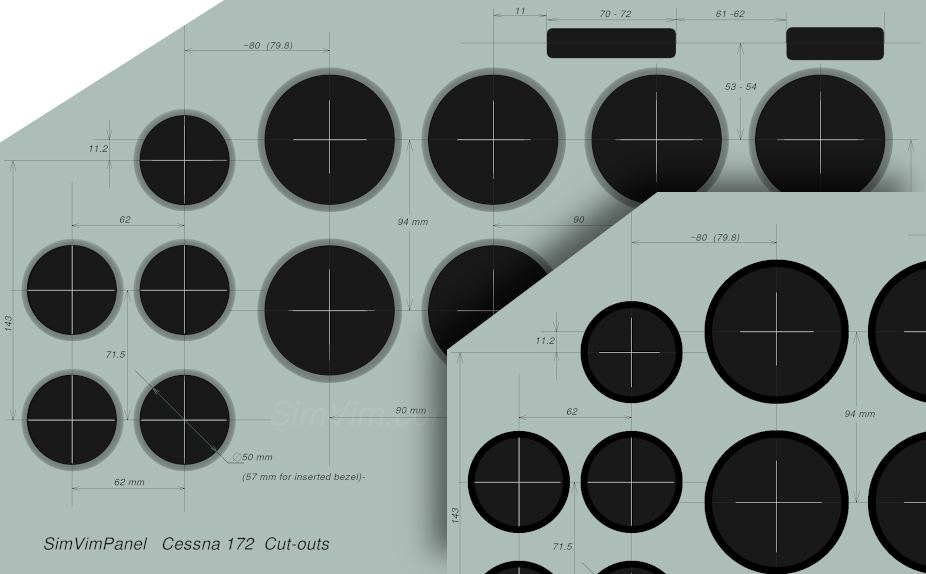
There are two methods of making bezels for cover panel. You can use the more simplified option where you have just a bezel outer ring with glass, glued to the panel surface. In this case you should have smaller diameter of the instrument cut-outs (70-72mm for 3.125" gauges)
Otherwise, you can make the bezels that are inserted into the cover plate of your panel. In this case you should cut the holes with full 79-80mm diameter.
Here are the cut-out dimensions (in real size, in mm, 140 DPI) for the Cessna172 SimVimX Panel. The template shows the central part of the panel with all correct distances between gauges, not linked with the monitor start coordinates, because you can place the panel as you need on any screen and save the position in the program.
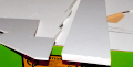
The full on-screen panel with all instruments in-place can prevent you from making the real yoke shaft, so you need to decide how to make it on needed hight. Here is an example how you could make it ( the second option is with "fake" foldable shaft):
Cessna 172 - Full Panel | Instrument Panel ->
This version of SimVim C172 panel is not intended for those who build a real instrument panel with cover plates and instrument cutouts, instead being for those who simply want to display a realistic high-resolution panel on their computer screen without anything extra.
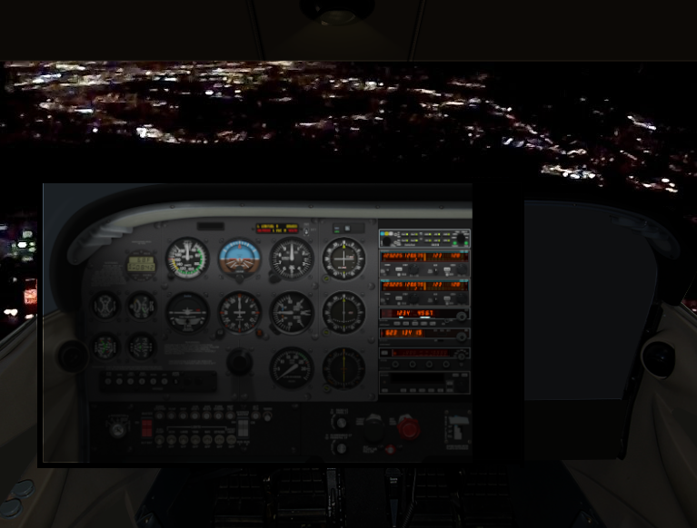
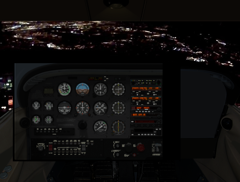
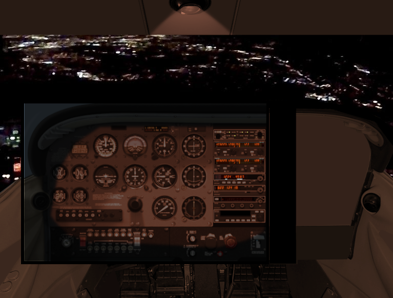
This textured full-sized SimVim panel can be used as-is on a screen of suitable size (30-40"). The panel has all on-screen controls fully functional (knobs, switches, buttons). The panel's brightness changes based on the simulator world's light level, and the panel includes custom lighting effects for different lighting channels, such as flood light, dome light, instrument and backlight brightness and radio display brightness.
You can run this panel in real size when all high-resolution instruments have the same dimensions as in real life, especially if you are using a large high-resolution monitor (more than 27-30").
The hidden parts of the panel (lower subpanel for example) can be viewed using the related SimVimX panel view control parameters (up/down/left/right) assigned to buttons.
Also, the panel can be displayed in scaled down ratio to fit any LCD screen size by pressing the "S" key to automatically scale the panel to screen size. Later, we will also include an option to assign a zoom parameter to buttons or an encoder in SimVimX..
This feature allows you to use the full panel module on any LCD screen (large monitor or notebook display). If you scale the panel down by 10-20% it will still be looking close to the real size with well readable hi-resolution instruments.
Panel Lighting/Brightness
All elements of the SimVim panel dim and change their visibility and color gradient depending on the time of day and weather. At night, the entire panel become dark with barely noticeable elements, with the exception of luminous devices such as numbers on the screens of radio receivers.
There are 3 options for lighting the panel instruments during night flight:
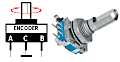
1) Glareshield flood light. This illumination is adjustable by the inner lower knob (GLARESHIELD LT) on the panel and can be controlled with the mouse wheel. In addition, you can assign the related SimVimX parameter (BRT_Pan_Flood) as an encoder or potentiometer and place it on a simple hardware panel below the monitor.
2) Panel LT. This is the lighting channel controlled with the outer upper knob on the panel adjusting the panel backlights (lettering) and optionally the main instruments backlights (see the note below).
3) Overhead flood lighting (Dome light).
The dome light floods the panel with a faint (reddish) light and makes it visible in total darkness.
Assign the related Dome Light/Brightness parameter as an encoder or analog axis and place it in your overhead. The SimVimPanel program will react to the dome light level to make the instrument panel more visible.
Optionally, you also can add a real dome lamp to lighten up your cockpit environment a bit, if needed.
NOTE: We can configure each instrument in a panel module to be equipped with internal illumination or not. In the current Cessna panel module, all the main instruments are equipped with internal lighting, but this can be changed.
GPS/NAV Switch
The panel has no GPS, but the NAV/GPS switch is present (above VOR #1). It is added in case you use a secondary small LCD display connected to your X-Plane computer with GPS (GNS530) dragged onto it.
Read this page on how to use an external LCD to display GPS.
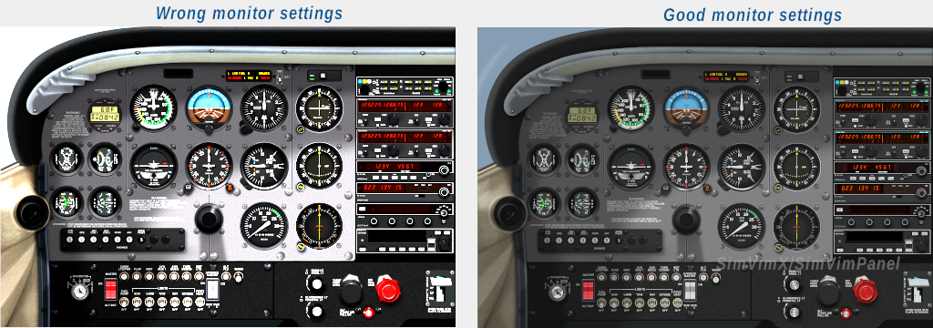
Although the panel is designed to respond to ambient light in the most realistic way depending on the time of day, you should adjust your monitor so that its brightness and contrast settings are not set too high, for most monitors medium settings should be the most comfortable (about 40-60% of maximum contrast and brightness).