Multi-position switches

Multiposition rotary switches are an essential part of the control system in many aircraft cockpits.
This type of switches is used mainly when you need to control one parameter that has more than two states, for example select one mode for radio equipment (e.g. transponder mode switch), set map range, select navigation source. Also such control actuators as flaps lever may be considered a multiposition switch.
Rotary switches for your home cockpit
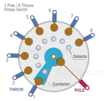
A rotary switch consists of a disc contactor (connected to pole terminal) operated by rotation of the spindle, and several contacts (connected to throw terminals) arranged in a circle along the contactor path. While you rotare an actuator (knob, handle), the "pole" disc connects to the "throw" contacts one by one.
Every rotary switch has a detent mechanism that allows it to "jump" from one position to another momentarily. As any other switches, rotary switch has at least one "Pole" terminal and several "Throw" terminals. Also, it can have several poles, each one commutating its own group of throw contacts.
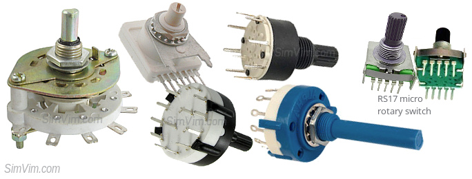

To make a rotary switch for your panel you need to buy a switch that has suitable size and positions number and find or make the knob yourself (using 3D-printing, for example). Then connect each position output terminal of this switch to digital inputs of the controller board.
Connection
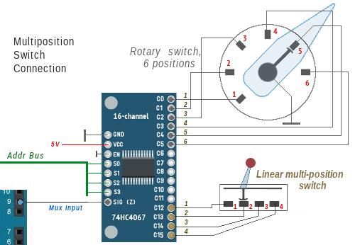
While you can connect a multi-position switch to multiple Arduino pins directly, it doesn't make sense in the SimVimX system, you should use the multiplexer inputs. The output terminals of each multi-position switch must be connected to adjacent inputs in ascending order.
Physically, a multi-position switch can be just a group of push-buttons for some equipment when each button switches this device into specific mode.

Using several momentary push-button switches
A multi-position switch can consist of a group of push-buttons, so you can make any mechanical actuator that has either linear or rotary movement. As example here is diagram for a 9-position flaps lever.

When the handle is pulled up no buttons are pressed, and when the lever is moved to the next position and released, the spring returns it down and the button in this position is actuated and stays pressed until the lever is moved again.
Besides, you may just have a group of momentary push-buttons on your aircraft panel, without any type of actuator, that will work the same way as multi-position switch. When you click one button, the parameter will take the value that is configured for its "position":
Multi-position switch alternatives
1. Binary Coded rotary switch
A HEX-code or "binary coded" rotary switch is similar to the regular rotary switch, but has the binary encoded outputs to save on pin requirements. Only 3 pins are required for 3-8 position switch, compared to 8
To make a switch with 3-8 positions you can buy one of the these cheap 8-position micro switches ($0.8 for a piece) with a long shaft, and it doesn't matter that it has 8 positions - you can only use a few of the first positions you need. See Sample Link on AliExpress and the Tech spec fie.
The switch has 4 pins labeled 1,2,4,8. You have to connect the first 3 (1,2,4) in this order to the digital inputs, that's all. (the central common "C" is center pole, connect it to GND):

From a users point of view, this switch works the same way as a simple rotary switch, just using only 3 inputs for any switch with 3-8 positions.
You can find that type of rotary switches sold as HEX, Binary or Decimal. All they are binary, and there is no difference in coding between Decimal and HEX besides the number of positions, the decimal means it has positions from 0 to 9, the Hex is from 0 to 15 (F). For now, the SimVimX plugin reads only 3 inputs for binary coding, just because rotary switches in a plane cockpit usually have less than 9 positions. But maybe it can extended later to 16 positions.
NOTE: There are also switches with Gray code output, like the Lorlin GCK1025 switches which have 3 pins. SimVimX doesn't support this, please take note.
2. Using an analog input
Alternatively, you can use any analog pin as an input for the voltage divider, but instead of a potentiometer, using a rotary switch that has a divider with multiple resistors (as in previous ArdSimX, XPData interfaces).
However, since SimVimX uses multiplexers, when assigning multi-position linear or rotary switches you can simply use a group of extended digital inputs where one input is assigned for each switch position.
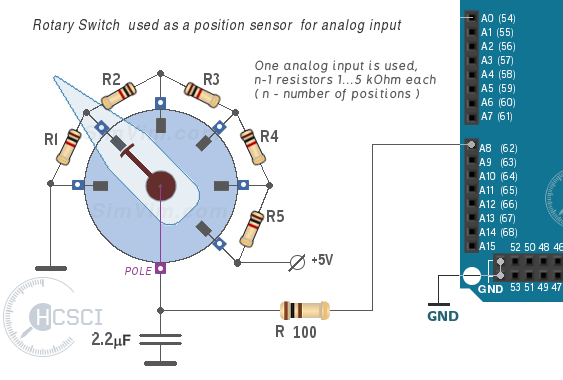
To prepare the rotary switch to act as a position sensor for an analog input, you need to solder a few resistors to the switch pins as shown in the diagram.
For an N-position rotary switch you will need N-1 resistors of the same value (1...5k each), soldered between consecutive terminals. The sum of all resistor values can be between 3...50 kOhm. The first terminal is connected to the GND bus, the last one - to +5V.
Also, one 100 ohm resistor and one 1..5 uF capacitor need to be connected to the pole terminal - the resistor goes to an analog input and the capacitor to the GND bus.
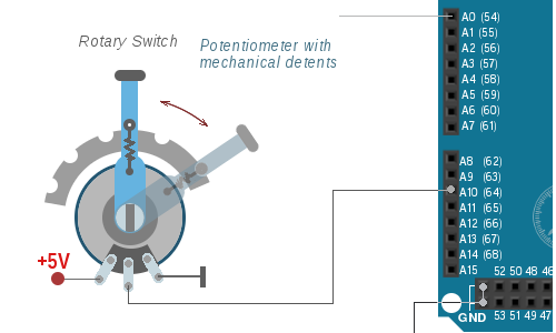
An easy way to make a multi-position switch for a lever or rotary switch is using a potentiometer connected to an analog input as usual. The potentiometer shaft is attached to the lever shaft and the lever has several mechanical locks. To use the full rotational range of the potentiometer, you can add gears between the lever axis and the potentiometer shaft.
Note: the method with a potentiometer (non-fixed resistors) can be used for rotary switches with fixed values. For example, if you have a range of parameter values from 0 to 5, you should have 6 equal position detents for your potentiometer.
This is also suitable for flaps lever.
In X-Plane any virtual model has a predefined number of flap lever detents that is read by the SimVimX plugin on start. The flaps position dataref value range is 0.00 to 1.00, and the lever position is always mapped into this range linearly!
For example, if your plane has 6 detents, the full dataref range will be divided as 1/5 - to these values: 0, 0.2, 0.4, 0.6, 0.8, 1.00. So, if you have mechanical detents on your lever that have unequal distances between them, you need to make a lever with several resistors, not a single potentiometer, or with several buttons on the multiplexer digital inputs (see the diagrams above).