Manual Electric Trim (MET)
How it works
The Electric Trim control is a "split" switch located on the control wheel. This allows the plane to be trimmed by your thumb, not using the trim wheel, located on the pedestal. Moving the switch up or down activates pitch trim servo which also results in movement of the trim wheel and disengages the autopilot if it was previously active.
A simple and obvious trim switch implementation is using the right switch as up/down trim commands actuator, and the left "ARM" switch as a circuit interrupter for the "command" switch, to prevent controlling the trim with the right switch only:


As you can see, to make these two-way switches you can use either a pair of momentary buttons (left circuit in the picture) or spring-loaded 3-position rocker switch (right circuit).
When the autopilot is engaged it controls the pitch trim servo. When disengaged, the electric trim may be freely used to command the pitch trim servo motor instead of autopilot. If the trim switch is moved while autopilot is engaged, it automatically disengages the AP (roll and pitch), not affecting the FD (flight director).
Why it's a split switch
You should move two switches simultaneously to control the trim servo, moving just one side of the switch shouldn't actuate the trim. If you hold one side of the split switch down for more than several seconds (depending on the aircraft), the trim switch will automatically become disabled.
Trim switch are split in two for safety. If it was a single switch you could accidentally bump the trim switch with your thumb at a very wrong time (and disengage AP). Also, a switch could get stuck and lead to fast dangerous overtrim.
One half of the switch can control the UP and DN pins to make the DC motor rotate in the desired direction. The other half can serve as a simple safety contact (see the shematic diagram below).
RSC/SimVimX MET functionality and motorized wheel
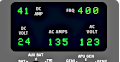
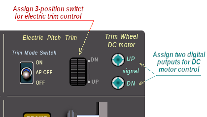
To assign the electric trim function in the configurator find the "Electric Pitch Trim" parameter (Elec_Trim) for 3-position Up / Dn switch.
Also, if you wish, you can use a motorized trim wheel to get more "realistic" flight environment using two output SimVimX signals ("Trim_Motor_Up" and "Trim_Motor_Dn").
NOTE: The "motorized" trim in your cockpit simulator can only be implemented as a dummy, it's just a motor that rotates the wheel when you use the electric trim switch or the autopilot is in one of the vertical axis modes. And it's just wheel rotation, a visual effect feature with no input to the simulator. This is why:
- The simulator manages the trim datarefs directly using the internal autopilot functions (when AP is enabled) and animates the virtual trim wheel rotation.
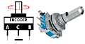
- The same trim datarefs can be set by the trim switch (electric trim commands) or using an encoder/potentiometer (for the trim wheel) in RSC/SimVimX.
- There is no way to get specific data from the simulator for a motorized wheel before the AP functions start to control the virtual trim.
- The only way to generate signals for the external trim motor when the virtual trim wheel is moving is using the trim up/down datarefs from the simulator.
- So, if the input device (encoder or potentiometer) is attached to the wheel and the motor is activated by the simulator, we should block the input signals to prevent the logical loop, else the encoder will change the trim dataref in conflict with AP/elec trim.
On the other hand, the input from the encoder should work when AP is disengaged (the wheel rotates manually) and it also should stay unblocked and functional in certain AP modes (when only lateral modes are engaged).
That's what the SimVimX/RSC system does - generates the output signals for the DC motor and controls the inputs reading depending on the AP modes.
Trim Wheel, DC Motor Control
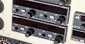
Two output SimVimX signals are used in RSC Interface to control the DC motor that rotates the trim wheel. Open the "Flight Controls" layout Map in the configurator and assign the digital outputs "Trim_Motor_Up" and "Trim_Motor_Dn"
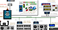
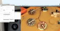
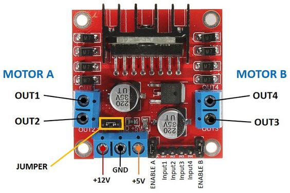
These two outputs can control a suitable DC motor driver (H-Bridge circuit board, such as L298N etc). For example, the board in the picture above can drive two DC motors. You need only one side (Motor A for example).
Connect the "Trim_Motor_Up" output to Input1 and "Trim_Motor_Dn" output to Input2. Use an appropriate voltage source for your DC motor (12v or either from 5 up to 35v depending on the motor). No need to connect the 5v input, but connect the GND of course.
! You must add a gearbox to get the desired speed of rotation of your wheel. For example the gearbox output shaft should rotate at the speed of one revolution of the wheel in 4-6 seconds for Cessna 172 and at a different speed for other planes.
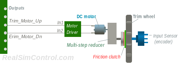
To be able to rotate the wheel freely by hand, a friction muff (disk with fabric friction material) can be added between the wheel and the disk on the gearbox output shaft. Mount and tighten them in a way that doesn't stop you from turning the wheel by hand, but has enough friction to allow the motor to turn the wheel.