|||>
| SimVimX System |
| HARDWARE
CONFIG TOOL
TECH TIPS |
| Panels
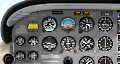
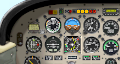
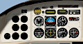
| Baron 58
SimVimX Configuration Tool

System Structure

I/O Extensios
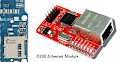
USB / LAN

Power

Components

Wiring Tips

My Test Panel

Input MUXs

Switches

3 Pos. Switch
Rotary Switch
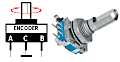
Encoder

Analog Input

Key-Matrix

LEDs
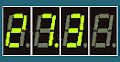
7-Segment
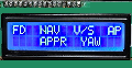
Character LCD

Servo Gauges

Coil Gauges

Stepper Gauges
Gauge Calibration
Main Configuration and Conversion Tool

How To Start

To Buy or Make it?

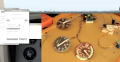
Prototiping, Workbench

Switch + LED

DIY Breakout

DIY 2x-Encoder

2-needle Gauge

DIY Gxxx

External GPS

A510 Starter
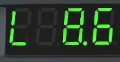
Trim Display

Electric Trim

Starter Return
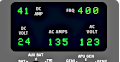
Elec Panel B737

FeedBack ???

Take photos